
Pesquisar nas perguntas frequentes (FAQ)
How to test InRow BMS/ModBus Communication?
Issue:
How can I test your InRow BMS/ModBus Communications?
Product line:
ACRC, ACRP, ACRD, ACSC
Environment:
InRow Cooling
Cause:
Resolution:
When troubleshooting an InRow for correct BMS communication, you need to know how to prove our equipment is passing its signal appropriately. Please use the instructions below to perform this test.
What you will need:
1. B&B Electronics Converter pn# 4850T9L [A 12vDC power supply is also required for power]
2. ModScan Software:
a. Demo download -- http://www.win-tech.com/html/demos.htm
i. Select ModScan32.zip (851K), download, and extract [unzip] to your desktop
Converter Configuration:
You will need to configure the RS-422/485 converter prior to making connections to test the BMS functionality. Remove the cover opposite the label and please make the configurations listed below
1. Dip switches: 1,3,4 off; 2,5,6,7,8 on; SD jumper is on; RTS jumper is off [see Figure 1 below]

Figure 1
2. Wire your 12vDC power supply to TB2. Red should go to +12vDC and black should go to GND [ground] [see Figure 1].
3. Wire your BMS connection wires to TB1 TDA(-) and TB1 TDB(+) as shown above.
4. If you are on site you may connect your wires to the InRow. The wires will be cross polarity. Therefore, on the converter TDA(-) crosses polarity on the InRow to D1(+) and TDB(+) crosses polarity on the InRow to D0(-) [see Figure 2 below].

Figure 2
1. Click OK – you do not need to fill anything out … this is a demo only mode

2. When you come to the next 2 screens give the page 10s to load and Click Ok
3. Select Connection >> Connect >> set appropriate Com port and Configuration [this should be set to whatever the InRow BMS baud rate is set to under Configure Modbus on the display. 8 data bits, no parity, 1 stop bit are fixed settings on the InRow display].

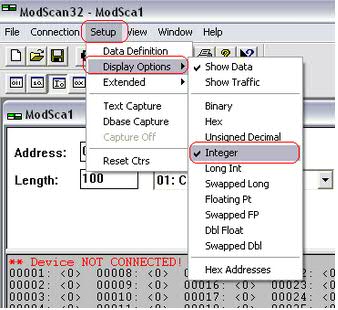
4. Next select Setup >> Display Options >> Integer
5. MODBUS Point Type: needs to be set to 03: HOLDING REGISTER; Address: needs to start on a known register; Length: needs to end on a known register
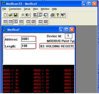
6. In the example below we are using an InRow RC. NOTE there is a It has the 0 and 1 offset option when using ModScan

How can I test your InRow BMS/ModBus Communications?
Product line:
ACRC, ACRP, ACRD, ACSC
Environment:
InRow Cooling
Cause:
Resolution:
When troubleshooting an InRow for correct BMS communication, you need to know how to prove our equipment is passing its signal appropriately. Please use the instructions below to perform this test.
What you will need:
1. B&B Electronics Converter pn# 4850T9L [A 12vDC power supply is also required for power]
2. ModScan Software:
a. Demo download -- http://www.win-tech.com/html/demos.htm
i. Select ModScan32.zip (851K), download, and extract [unzip] to your desktop
Converter Configuration:
You will need to configure the RS-422/485 converter prior to making connections to test the BMS functionality. Remove the cover opposite the label and please make the configurations listed below
1. Dip switches: 1,3,4 off; 2,5,6,7,8 on; SD jumper is on; RTS jumper is off [see Figure 1 below]
Figure 1
2. Wire your 12vDC power supply to TB2. Red should go to +12vDC and black should go to GND [ground] [see Figure 1].
3. Wire your BMS connection wires to TB1 TDA(-) and TB1 TDB(+) as shown above.
4. If you are on site you may connect your wires to the InRow. The wires will be cross polarity. Therefore, on the converter TDA(-) crosses polarity on the InRow to D1(+) and TDB(+) crosses polarity on the InRow to D0(-) [see Figure 2 below].
Figure 2
ModScan Configuration:
1. Click OK – you do not need to fill anything out … this is a demo only mode
2. When you come to the next 2 screens give the page 10s to load and Click Ok
3. Select Connection >> Connect >> set appropriate Com port and Configuration [this should be set to whatever the InRow BMS baud rate is set to under Configure Modbus on the display. 8 data bits, no parity, 1 stop bit are fixed settings on the InRow display].
4. Next select Setup >> Display Options >> Integer
5. MODBUS Point Type: needs to be set to 03: HOLDING REGISTER; Address: needs to start on a known register; Length: needs to end on a known register
6. In the example below we are using an InRow RC. NOTE there is a It has the 0 and 1 offset option when using ModScan
7. For any 600mm unit you want to make sure the P2 connection to J84.1-3 are correctly wired.
Publicado para:Schneider Electric Portugal
Explorar mais