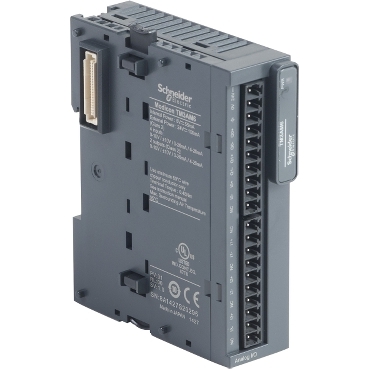
Roll over image to zoom in

TM3AM6
Expansion I/O modules for Modicon M221, M241, M251 and M262 controllers
Modularity and easness of installation
Large choice of I/O system to enhance the capabilities of Modicon M2xx plc
Intuitive machine programming with EcoStruxure Machine Expert
Modicon TM3 system allows to Modicon M2xx plc flexible and customizable I/O extension
Environmental Data
Total lifecycle Carbon footprint
64
Use Better
Packaging made with recycled cardboard
Yes
Use Again
Take-back
No
Compatible Software
SRVEW1YMSL01
This product is part of the Modicon TM3 range, an offer of expansion I/O modules for Modicon M221, M241, M251 and M262. The analogue I/O module provides 4 inputs and 2 outputs with 11bit + sign and 12bit input resolution. It is an I/O module with a rated supply voltage of 24V DC, a current consumption of 45mA, 55mA at 5V DC via bus connector, 55mA, 100mA at 24V DC via external supply. This product is capable of controlling variable speed drives or any device equipped with a current or voltage input. There is an insulation between input and supply at 1500V AC, input and internal logic at 500V AC, output and supply at 1500V AC and output and internal logic at 500V AC. It is furnished with removable screw terminal for electrical connection with 3.18mm pitch adjustment for inputs and supply. It is an IP20 rated product. Its dimensions are 23.6mm (Width) x 70mm (Depth) x 90mm (Height). It weighs 0.11kg. This product is certified by CE. It meets EN/IEC 61131-2 and EN/IEC 61010-2-201 standards. This module is compatible with Modicon M262, Modicon M241, Modicon M251 and Modicon M221 logic controller. It supports top hat type TH35-15, top hat type TH35-7.5 rail conforming to IEC 60715 and plate or panel with fixing kit mount. Modicon TM3 expansion modules have been designed with a simple interlocking assembly mechanism. A bus expansion connector is used to distribute data and the power supply when assembling the Modicon TM3 modules with logic controllers. Boost the performance of your controller with the Modicon TM3 I/O system specially designed for the Modicon M221, M241 and M251 logic controllers.
Range of product | Modicon TM3 |
---|---|
Product or component type | Input/output analog module |
Range compatibility | Modicon M221 Modicon M241 Modicon M251 Modicon M262 |
Analogue input number | 4 |
Analogue input type | current 4...20 mA current 0...20 mA voltage 0...10 V voltage - 10...10 V |
Analogue output number | 2 |
Analogue output type | Current: 4...20 mA Current: 0...20 mA Voltage: 0...10 V Voltage: - 10...10 V |
Analogue input resolution | 12 bits 11 bits + sign |
---|---|
Permissible continuous overload | 13 V, analogue input type: voltage 40 mA, analogue input type: current |
Input impedance | <= 50 Ohm current >= 1 MOhm voltage |
Analogue output resolution | 12 bits 11 bits + sign |
LSB value | 2.44 mV 0...10 Vvoltage 4.88 mV - 10...10 Vvoltage 4.88 µA 0...20 mAcurrent 3.91 µA 4...20 mAcurrent |
load type | Resistive |
Load impedance ohmic | 1 kOhm voltage 300 Ohm current |
Stabilisation time | 1 ms |
Conversion time | 1 ms + 1 ms per channel + 1 controller cycle time |
Sampling duration | 1 ms 10 ms |
Absolute accuracy error | +/- 1 % of full scale +/- 0.2 % of full scale at 25 °C |
Temperature drift | +/- 0.01 %FS/°C |
Repeat accuracy | +/-0.5 %FS for input +/-0.5 %FS for output |
Non-linearity | +/- 0.2 %FS |
Output ripple | 20 mV |
Cross talk | <= 1 LSB |
[Us] rated supply voltage | 24 V DC |
Supply voltage limits | 20.4…28.8 V |
Type of cable | Twisted shielded pairs cable <30 m for input/output circuit |
Current consumption | 45 mA at 5 V DC via bus connector no load 55 mA at 5 V DC via bus connector full load 55 mA at 24 V DC via external supply no load 100 mA at 24 V DC via external supply full load |
Local signalling | 1 LED (green) for PWR |
Electrical connection | 10 x 1.5 mm² removable screw terminal block with pitch 3.81 mm adjustment for inputs 10 x 1.5 mm² removable screw terminal block with pitch 3.81 mm adjustment for inputs, outputs and supply |
Insulation | Between input and supply at 1500 V AC Between input and internal logic at 500 V AC Between output and supply at 1500 V AC Between output and internal logic at 500 V AC |
Marking | CE |
Surge withstand | 1 kV power supply common mode conforming to IEC 61000-4-5 0.5 kV power supply differential mode conforming to IEC 61000-4-5 1 kV I/O common mode conforming to IEC 61000-4-5 0.5 kV I/O differential mode conforming to IEC 61000-4-5 |
Mounting support | Top hat type TH35-15 rail conforming to IEC 60715 Top hat type TH35-7.5 rail conforming to IEC 60715 plate or panel with fixing kit |
Height | 90 mm |
Depth | 70 mm |
Width | 23.6 mm |
Net weight | 0.11 kg |
Standards | IEC 61131-2 |
---|---|
Product certifications | CE UKCA RCM EAC cULus cULus HazLoc |
Resistance to electrostatic discharge | 8 kV in air conforming to IEC 61000-4-2 4 kV on contact conforming to IEC 61000-4-2 |
Resistance to electromagnetic fields | 10 V/m 80 MHz...1 GHz conforming to IEC 61000-4-3 3 V/m 1.4 GHz...2 GHz conforming to IEC 61000-4-3 1 V/m 2 GHz...3 GHz conforming to IEC 61000-4-3 |
Resistance to magnetic fields | 30 A/m conforming to IEC 61000-4-8 |
Resistance to fast transients | 1 kV (I/O) conforming to IEC 61000-4-4 |
Resistance to conducted disturbances | 10 V 0.15...80 MHz conforming to IEC 61000-4-6 3 V spot frequency (2, 3, 4, 6.2, 8.2, 12.6, 16.5, 18.8, 22, 25 MHz) conforming to Marine specification (LR, ABS, DNV, GL) |
Electromagnetic emission | Radiated emissions - test level: 40 dBμV/m QP class A ( 10 m) at 30…230 MHz conforming to IEC 55011 Radiated emissions - test level: 47 dBμV/m QP class A ( 10 m) at 230…1000 MHz conforming to IEC 55011 |
Immunity to microbreaks | 10 ms |
Ambient air temperature for operation | -10…55 °C horizontal installation -10…35 °C vertical installation |
Ambient air temperature for storage | -25…70 °C |
Relative humidity | 10…95 %, without condensation (in operation) 10…95 %, without condensation (in storage) |
IP degree of protection | IP20 |
Pollution degree | 2 |
Operating altitude | 0...2000 m |
Storage altitude | 0…3000 m |
Vibration resistance | 3.5 mm at 5…8.4 Hz on DIN rail 3 gn at 8.4…150 Hz on DIN rail |
Shock resistance | 15 gn for 11 ms |
Unit Type of Package 1 | PCE |
---|---|
Number of Units in Package 1 | 1 |
Package 1 Height | 7.500 cm |
Package 1 Width | 10.500 cm |
Package 1 Length | 12.500 cm |
Package 1 Weight | 214.000 g |
Unit Type of Package 2 | S04 |
Number of Units in Package 2 | 42 |
Package 2 Height | 30.000 cm |
Package 2 Width | 40.000 cm |
Package 2 Length | 60.000 cm |
Package 2 Weight | 10.027 kg |
Schneider Electric aims to achieve Net Zero status by 2050 through supply chain partnerships, lower impact materials, and circularity via our ongoing “Use Better, Use Longer, Use Again” campaign to extend product lifetimes and recyclability.
Total lifecycle Carbon footprint
64
Environmental Disclosure
Use Better
Packaging made with recycled cardboard
Yes
Packaging without single use plastic
Yes
Pro-active compliance (Product out of EU RoHS legal scope)
SCIP Number
3b9533ee-f829-495f-9b87-8bb0822090f1
REACh Regulation
PVC free
Yes
Use Again
End of life manual availability
Take-back
No
WEEE Label

The product must be disposed on European Union markets following specific waste collection and never end up in rubbish bins
Dimensions
(*) 8.5 mm/0.33 in when the clamp is pulled out.
Spacing Requirements
Mounting on a Rail
Incorrect Mounting
Mounting on a Panel Surface
(1) Install a mounting strip
Mounting Hole Layout
Analogue Mixed I/O Module
Wiring Diagram (Current / Voltage)
(*) Type T fuse
(1) Current/Voltage analog output device
(2) Current/Voltage analog input device
Items usually bought together
Need more information? Check our technical FAQs!
Easily find answers to the most frequently asked questions.