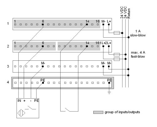
The wiring diagram below shows an example of a sensor activated by an output. The diagram shows the sensors being supplied with voltage only when the outputs on pins 6 and 14, row 2, are high.
The inputs from pins 6 and 14, row 1, can be high only when one of the associated outputs is high.
Separate connections to pins 17 and 18 are shown on row 3, even though these two pins are internally connected. This is done to halve the load.
The inputs from pins 6 and 14, row 1, can be high only when one of the associated outputs is high.
Separate connections to pins 17 and 18 are shown on row 3, even though these two pins are internally connected. This is done to halve the load.
Released for: Schneider Electric India
