


How do we configure a Varlogic RT controller?
Following is a general QuickStart for basic configuration of the RT6, RT8 or RT12 controllers.
For detailed explanations, please find the user manual attached to the FAQ.
Wiring
Wiring must be done according to schematic found on page 1 section 4.
The CT must be mounted to P1. P2 must be connected to the 400V terminal. P3 must be connected to the 0V terminal.
This is important as the controller uses the connections to take the correct readings and apply the power factor correction required.
Configuration
The following are the minimum required information for programming the controller.
- Number of capacitors (steps).
- Capacitor values from smallest to largest.
- CT primary value. Must be 5 at the secondary of the CT (see page 4, section 6.8).
Here are the paramaters to be configured.
- 5.3 -> CosPHI
- 5.5 -> STEP
- 5.6 -> PROGRAM
- 5.7 -> C/K
- 5.8 -> CT
Example Configuration
Configure the RT6 with the following known information.
- Number of capacitors (steps) = 5
- Capacitor values (kVAR) = 12, 12, 25, 33, 33
- CT = 1250/5
5.3 -> CosPHI = 0.95
This value is provided by the client, integrator or may be kept at default.
5.5 -> STEP = 5
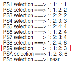
5.6 -> Pro9 = PS9
This is given by the ratios available on page 3 of the manual (section 6.4). The ratios all based on the first capacitor value. For this example, the ratios are: 1:1:2:3:3. It is an approximation and some cases may be possible for 2 program selections. From the table gives PS9 for our ratio.
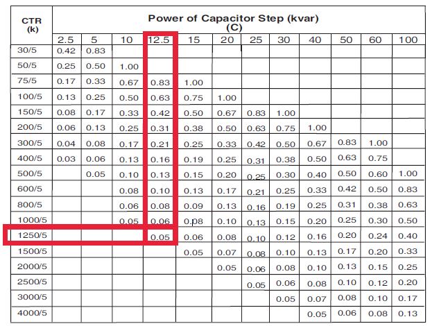
5.7 -> C/K = 0.05
This can be attained from the table on page 4, section 6.6. Look down the CTR column and across to the first capacitor step value.
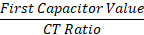
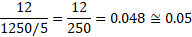
It may also be calculated by the following formula:
For detailed explanations, please find the user manual attached to the FAQ.
Wiring
Wiring must be done according to schematic found on page 1 section 4.
The CT must be mounted to P1. P2 must be connected to the 400V terminal. P3 must be connected to the 0V terminal.
This is important as the controller uses the connections to take the correct readings and apply the power factor correction required.
Configuration
The following are the minimum required information for programming the controller.
- Number of capacitors (steps).
- Capacitor values from smallest to largest.
- CT primary value. Must be 5 at the secondary of the CT (see page 4, section 6.8).
Here are the paramaters to be configured.
- 5.3 -> CosPHI
- 5.5 -> STEP
- 5.6 -> PROGRAM
- 5.7 -> C/K
- 5.8 -> CT
- Entering program mode, press SET button for 3 seconds.
- UP and DOWN arrows are used to scroll between parameters and modify values.
- Press SET to enter the parameter adjustment.
- After adjusting to the required value, pressing SET will accept the new value and the controller returns to normal operating mode.
Example Configuration
Configure the RT6 with the following known information.
- Number of capacitors (steps) = 5
- Capacitor values (kVAR) = 12, 12, 25, 33, 33
- CT = 1250/5
5.3 -> CosPHI = 0.95
This value is provided by the client, integrator or may be kept at default.
5.5 -> STEP = 5
5.6 -> Pro9 = PS9
This is given by the ratios available on page 3 of the manual (section 6.4). The ratios all based on the first capacitor value. For this example, the ratios are: 1:1:2:3:3. It is an approximation and some cases may be possible for 2 program selections. From the table gives PS9 for our ratio.
5.7 -> C/K = 0.05
This can be attained from the table on page 4, section 6.6. Look down the CTR column and across to the first capacitor step value.
It may also be calculated by the following formula: