
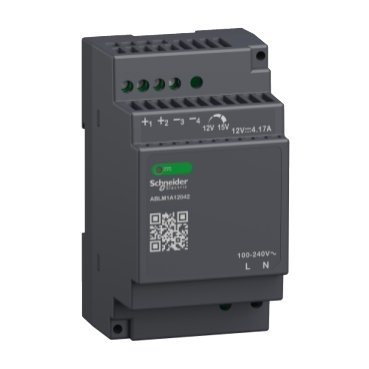


ABLM1A12042
| Range of product | Modicon Power Supply |
|---|---|
| Product or component type | Power supply |
| Power supply type | Regulated switch mode |
| Variant option | Modular |
| Enclosure material | Plastic |
| Nominal input voltage | 100...240 V AC single phase 100...240 V AC phase to phase |
| Rated power in W | 50 W |
| Output voltage | 12 V DC |
| Power supply output current | 4.17 A |
| Input voltage limits | 90...264 V AC |
|---|---|
| Nominal network frequency | 50…60 Hz |
| Network system compatibility | TN TT IT |
| Maximum leakage current | 0.25 mA 240 V AC |
| Input protection type | Integrated fuse (not interchangeable) 3.15 A External protection (recommended) 20 A Curve B External protection (recommended) 20 A Curve C External protection (recommended) 10 A Curve B External protection (recommended) 6 A Curve C |
| Inrush current | 30 A at 115 V 60 A at 230 V |
| Power factor | 0.50 at 115 V AC 0.39 at 230 V AC |
| Efficiency | 88 % at 115 V AC 88 % at 230 V AC |
| Output voltage adjustment | 12...15 V |
| Power dissipation in W | 5.5 W |
| Current consumption | < 1.5 A 115 V AC < 1 A 230 V AC |
| Turn-on time | < 2 s |
| Holding time | > 20 ms 115 V AC > 60 ms 230 V AC |
| Startup with capacitive loads | 3000 µF |
| Residual ripple | < 100 mV |
| Meantime between failure [MTBF] | 1500000 h at 25 °C, full load 1000000 h at 55 °C, 80 % load |
| Output protection type | Against overload and short-circuits, protection technology: automatic reset Against over temperature, protection technology: manual reset Against overvoltage, protection technology: manual reset |
| Connections - terminals | Screw connection: 0.5...2.5 mm², (AWG 20...AWG 14) without wire end ferrule for output Screw connection: 0.5...1.5 mm², (AWG 20...AWG 16) with wire end ferrule for output Screw connection: 0.5...1.5 mm², (AWG 20...AWG 16) for input |
| Line and load regulation | < 0.5 % at in line < 1 % at 0 to 100 % load |
| Status LED | 1 LED (green) output voltage |
| Depth | 55.6 mm |
| Height | 91 mm |
| Width | 53 mm |
| Net weight | 0.221 kg |
| Output coupling | Serial Parallel |
| Mounting support | Top hat type TH35-15 rail conforming to IEC 60715 Top hat type TH35-7.5 rail conforming to IEC 60715 Double-profile DIN rail panel mounting |
| Supply | SELV conforming to IEC 60950-1 SELV conforming to IEC 60204-1 SELV conforming to IEC 60364-4-41 |
| Dielectric strength | 3000 V AC input/output |
| Service life | 10 year(s) |
| Overvoltage category | II |
| Standards | IEC 62368-1 EN/IEC 61010-1 EN 61010-2-201 EN/IEC 61204-3 IEC 61000-6-1 IEC 61000-6-2 IEC 61000-6-3 IEC 61000-6-4 IEC 61000-3-2 EN 61000-3-3 UL 62368-1 UL 61010-1 UL 61010-2-201 CSA C22.2 No 62368-1 CSA C22.2 No 61010-1 CSA C22.2 No 61010-2-201 |
|---|---|
| Product certifications | CE CUL listed CUL recognized RCM CB Scheme EAC KC NEC: class 2 |
| Operating altitude | < 2000 m overvoltage category III 2000 m...5000 m overvoltage category II |
| Shock resistance | 150 m/s² for 11 ms |
| IP degree of protection | IP20 |
| Ambient air temperature for operation | -25…55 °C without current derating mounting position A < 2000 m 55…70 °C with current derating of 2.67 % per °C mounting position A < 2000 m |
| Electrical shock protection class | Class II without PE connection |
| Pollution degree | 2 |
| Vibration resistance | 3 mm (f= 2…9 Hz) conforming to IEC 60721-3-3 10 m/s² (f= 9…200 Hz) conforming to IEC 60721-3-3 |
| Electromagnetic immunity | Immunity to electrostatic discharge - test level: 8 kV (contact discharge) conforming to IEC 61000-4-2 Immunity to electrostatic discharge - test level: 15 kV (air discharge) conforming to IEC 61000-4-2 Electromagnetic field immunity test - test level: 15 V/m (80 MHz...2 GHz) conforming to IEC 61000-4-3 Electromagnetic field immunity test - test level: 5 V/m (2...2.7 GHz) conforming to IEC 61000-4-3 Electromagnetic field immunity test - test level: 5 V/m (2.7...6 GHz) conforming to IEC 61000-4-3 Immunity to fast transients - test level: 4 kV (on input-output) conforming to IEC 61000-4-4 Surge immunity test - test level: 4 kV (between power supply and earth) conforming to IEC 61000-4-5 Surge immunity test - test level: 3 kV (between phases) conforming to IEC 61000-4-5 Immunity to conducted disturbances - test level: 15 V (0.15...80 MHz) conforming to IEC 61000-4-6 Immunity to magnetic fields - test level: 30 A/m (50...60 Hz) conforming to IEC 61000-4-8 Immunity to voltage dips - test level: 100 % (1 cycle) conforming to IEC 61000-4-11 Immunity to voltage dips - test level: 60 % (10 cycles) conforming to IEC 61000-4-11 Immunity to voltage dips - test level: 30 % (25 cycles) conforming to IEC 61000-4-11 Disturbing field emission conforming to EN 55016-2-3 Limits for harmonic current emissions conforming to IEC 61000-3-2 conforming to EN 55016-1-2 conforming to EN 55016-2-1 |
| Electromagnetic emission | Conducted emissions conforming to IEC 61000-6-3 Radiated emissions conforming to IEC 61000-6-4 |
| Unit Type of Package 1 | PCE |
|---|---|
| Number of Units in Package 1 | 1 |
| Package 1 Height | 6.100 cm |
| Package 1 Width | 6.100 cm |
| Package 1 Length | 11.000 cm |
| Package 1 Weight | 228.000 g |
| Unit Type of Package 2 | S02 |
| Number of Units in Package 2 | 24 |
| Package 2 Height | 15.000 cm |
| Package 2 Width | 30.000 cm |
| Package 2 Length | 40.000 cm |
| Package 2 Weight | 5.819 kg |
If the unit is use in a manner not specified by the manufacturer, the protection provided by the equipment may be impaired.
For means of disconnection a switch or circuit breaker, located near the product, must be included in the installation. A marking as disconnecting device for the product is required.
The device has an internal fuse. The unit is tested and approved with branch circuit protective device up to 20A. This circuit breaker can be used as disconnecting device.
The power supply is only suitable for audio, video, information, communication, industrial and control equipment.


(1) : Load

(1) : Load
ABLx1Axxxxx-1 = ABLx1Axxxxx-2
max 2 x ABLx1Axxxxx
L1 = L2
∆V max 25 mV
ILoad < 90% 2 x Inom

(1) : RLoad1
(2) : RLoad2
RLoad1= RLoad2
I1 = I2 = ~ Inom

(1) : Vout1
(2) : Vout2
(3) : 2 x Diode, VRRM> 2 x Vout1/2, IF > 2 x Inom1/2
(4) : VLoad = 2 x Vout
(5) : Load

(1) : Ambient


X : Ambient Temperature (ºC)
Y : Percentage of Max Load (%)
1 : Altitude @2000M with Mounting A
2 : Altitude @5000M with Mounting A
3 : Altitude @2000M with Mounting B
4 : Altitude @5000M with Mounting B
Need more information? Check our technical FAQs!
Easily find answers to the most frequently asked questions.