
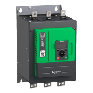


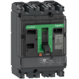
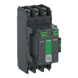
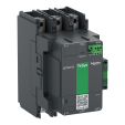
ATS480C17Y


SRVEW1YDRV10
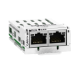
SRVEW3YDRV10
| Range of product | Altivar Soft Starter ATS480 |
|---|---|
| Product or component type | Soft starter |
| Product destination | Asynchronous motors |
| Product specific application | Process and infrastructures |
| Device short name | ATS480 |
| Network number of phases | 3 phases |
| Utilisation category | AC-3A AC-53A |
| Ue power supply voltage | 208...690 V - 15...10 % |
| power supply frequency | 50...60 Hz - 20...20 % |
| [Ie] rated operational current | Normal duty: 170.0 A (at <40 °C) |
| rated current in heavy duty | 140.0 A at 40 °C for heavy duty |
| IP degree of protection | IP00 |
| Motor power kW | 45.0 kW at 230 V in the motor supply line normal duty 37.0 kW at 230 V in the motor supply line heavy duty 90.0 kW at 400 V in the motor supply line normal duty 75.0 kW at 400 V in the motor supply line heavy duty 90.0 kW at 440 V in the motor supply line normal duty 75.0 kW at 440 V in the motor supply line heavy duty 110.0 kW at 500 V in the motor supply line normal duty 90.0 kW at 500 V in the motor supply line heavy duty 110.0 kW at 525 V in the motor supply line normal duty 90.0 kW at 525 V in the motor supply line heavy duty 132.0 kW at 660 V in the motor supply line normal duty 110.0 kW at 660 V in the motor supply line heavy duty 160.0 kW at 690 V in the motor supply line normal duty 110.0 kW at 690 V in the motor supply line heavy duty 90.0 kW at 230 V to the motor delta terminals normal duty 75.0 kW at 230 V to the motor delta terminals heavy duty 132.0 kW at 400 V to the motor delta terminals normal duty 110.0 kW at 400 V to the motor delta terminals heavy duty |
| Motor power hp | 50.0 hp at 208 V normal duty 40.0 hp at 208 V heavy duty 60.0 hp at 230 V normal duty 50.0 hp at 230 V heavy duty 125.0 hp at 460 V normal duty 100.0 hp at 460 V heavy duty 150.0 hp at 575 V normal duty 125.0 hp at 575 V heavy duty |
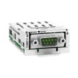
| Option card | Communication module for Profibus DP V1 Communication module for Modbus TCP/EtherNet/IP Communication module for CANopen daisy chain Communication module for CANopen Sub-D Communication module for CANopen open style Communication module for PROFINET |
| Device connection | In the motor supply line To the motor delta terminals |
|---|---|
| [Us] control circuit voltage | 110...230 V AC 50/60 Hz - 15...10 % |
| Apparent power | 0.09 kVA |
| Integrated motor overload protection | True |
| motor thermal protection class | Class 10E |
| Protection type | Phase failure: line Integrated thermal protection: motor Thermal protection: starter Current overload: motor Underload: motor Excessive starting time, locked rotor: motor Motor phase loss: motor Line supply phase loss: line Line supply phase loss: motor Thermal protection: motor |
| current limiting %In (5 x Ie maximum) | 150…700 % |
| Rated current pwr loss specification | 170.0 A |
| Power loss static current independent | 25.0 W |
| Power loss per device current dependent | 459.0 W |
| Standards | IEC 60947-4-2 UL 60947-4-2 IEC 60664-1 |
| Product certifications | CE cULus CCC UKCA RCM EAC DNV ABS BV CCS |
| Marking | CE CCC UKCA EAC RCM CULus |
| [Uc] control circuit voltage | 24 V DC |
| Discrete input number | 4 |
| Discrete input type | (STOP) logic inputs, 3500 Ohm (RUN) logic inputs, 3500 Ohm (DI3) programmable as logic input, 3500 Ohm (DI4) programmable as logic input, 3500 Ohm |
| Input compatibility | STOP: discrete input level 1 PLC conforming to IEC 61131-2 RUN: discrete input level 1 PLC conforming to IEC 61131-2 DI3: discrete input level 1 PLC conforming to IEC 61131-2 DI4: discrete input level 1 PLC conforming to IEC 61131-2 |
| Discrete input logic | Programmable digital input at State 0: < 5 V |
| Relay output number | 3 |
| Relay output type | Relay outputs R1A 1 NO Relay outputs R1B 1 NO Relay outputs RIC NO/NC programmable |
| Minimum switching current | 100 mA at 12 V DC for relay outputs |
| Maximum switching current | Relay outputs 2 A at 250 V AC Relay outputs 2 A at 30 V DC Relay outputs |
| Discrete output number | 2 |
| Discrete output type | (DQ1) programmable digital output <= 30 V (DQ2) programmable digital output <= 30 V |
| Output compatibility | Open collector level 1 PLC conforming to IEC 65A-68 |
| Analogue input number | 1 |
| Analogue input type | AI1/PTC PTC/Pt 100 temperature probe PTC2 PTC/Pt 100 temperature probe PTC3 PTC/Pt 100 temperature probe |
| Analogue output number | 1 |
| Analogue output type | Current output AQ1: 0...20 mA or 0...10 V, impedance <500 Ohm |
| Communication port protocol | Modbus serial |
| Connector type | 1 RJ45 |
| Communication data link | Serial |
| Physical interface | 2-wire RS 485 |
| Transmission rate | 1200...256000 bit/s |
| Transmission frame | RTU |
| Data format | 8 bits, configurable odd, even or no parity |
| Type of polarization | No impedance for Modbus serial |
| Number of addresses | 0…227 for Modbus serial |
| Method of access | Slave Modbus serial |
| Function available | External bypass control Pre-heating Smoke extraction Multi-motor cascade Second motor set User management Ports and services hardening Security event logging Cybersecure firmware update Single direction |
| Display screen available | True |
| Operating position | Vertical +/- 10 degree |
| Height | 340.0 mm |
| Width | 200.0 mm |
| Depth | 272.0 mm |
| Net weight | 12.4 kg |
| Electromagnetic compatibility | Conducted and radiated emissions level A conforming to IEC 60947-4-2 Conducted and radiated emissions with bypass level B conforming to IEC 60947-4-2 Damped oscillating waves level 3 conforming to IEC 61000-4-12 Electrostatic discharge level 3 conforming to IEC 61000-4-11 Immunity to electrical transients level 4 conforming to IEC 61000-4-4 Immunity to radiated radio-electrical interference level 3 conforming to IEC 61000-4-3 Voltage/current impulse level 3 conforming to IEC 61000-4-5 |
|---|---|
| Pollution degree | Level 3 |
| [Uimp] rated impulse withstand voltage | 6 kV |
| [Ui] rated insulation voltage | 690 V |
| Environmental class (during operation) | Class 3C3 according to IEC 60721-3-3 Class 3S2 according to IEC 60721-3-3 |
| Relative humidity | 0…95 % without condensation or dripping water conforming to IEC 60068-2-3 |
| Ambient air temperature for operation | 40…60 °C (with current derating of 2 % per °C) -15…40 °C (without derating) |
| Ambient air temperature for storage | -25…70 °C |
| Operating altitude | <= 1000 m without derating > 1000...4000 m with current derating 1 % per 100 m |
| Maximum deflection under vibratory load (during operation) | 1.5 mm at 2...13 Hz |
| Maximum deflection under vibratory load (during storage) | 1.75 mm at 2...9 Hz |
| Maximum deflection under vibratory load (during transport) | 1.75 mm at 2...9 Hz |
| Maximum acceleration under vibrational stress (during operation) | 10 m/s² at 13...200 Hz |
| Maximum acceleration under vibratory load (during storage) | 15 m/s² at 200...500 Hz 10 m/s² at 9...200 Hz |
| Maximum acceleration under vibratory load (during transport) | 15 m/s² at 200...500 Hz 10 m/s² at 9...200 Hz |
| Maximum acceleration under shock impact (during operation) | 150 m/s² at 11 ms |
| Maximum acceleration under shock load (during storage) | 100 m/s² at 11 ms |
| Maximum acceleration under shock load (during transport) | 100 m/s² at 11 ms |
| Unit Type of Package 1 | PCE |
|---|---|
| Number of Units in Package 1 | 1 |
| Package 1 Height | 43.0 cm |
| Package 1 Width | 32.0 cm |
| Package 1 Length | 45.5 cm |
| Package 1 Weight | 14.367 kg |
| Unit Type of Package 2 | S06 |
| Number of Units in Package 2 | 2 |
| Package 2 Height | 75.0 cm |
| Package 2 Width | 60.0 cm |
| Package 2 Length | 80.0 cm |
| Package 2 Weight | 41.8 kg |


(1) : Mains side
(2) : Motor side
1/L1, 3/L2, 5/L3 : Mains supply inputs
2/T1, 4/T2, 6/T3 : Outputs to motor
A2, B2, C2 : Soft starter bypass

(1) : Installation of additional fast-acting fuses to upgrade to type 2 coordination according to IEC 60947–4–2.
(2) : Take into account the electrical characteristics of the relays (Control Terminal Characteristics).
(3) : The transformer must supply 110...230 VAC +10% — 15%, 50/60Hz.
(4) : RUN and STOP Management (3-wire control).
(5) : RUN and STOP Management (2-wire control).

(1) : Installation of additional fast-acting fuses to upgrade to type 2 coordination according to IEC 60947–4–2.
(2) : Take into account the electrical characteristics of the relays (Control Terminal Characteristics).
(3) : The transformer must supply 110...230 VAC +10% – 15%, 50/60Hz.
(4) : Take into account the electrical characteristics of the relays, especially when connecting to high rating contactor (Control Terminal Characteristics).
(5) : RUN and STOP Management (3-wire control).
(6) : RUN and STOP Management (2-wire control).
(7) : PC or PLC control

(1) : Control power supply 110-230 VAC
(2) : External supply 24 VDC
(3) : 2 Wires PTC/PT100
R1A, R1C, R3A, R3C : Sequence relay
R2A, R2C : End of start
STOP, RUN, DI3, DI4 : Digital inputs
AQ1 : Analogue output
PTC1/AI1, PTC2, PTC3 : PTC or PT100 connection
DQ1, DQ2, DQ+ : Digital outputs

Items usually bought together
Need more information? Check our technical FAQs!
Easily find answers to the most frequently asked questions.