
Roll over image to zoom in


+ 4
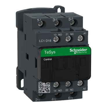
LC1D18F7
New modern look & feel of all machines
Easier to install and operate with multi-standard screws
Improved fire resistancy with IEC 60335-1(Clause 30.2) certificate by authorized agency
Anti-flammable refrigerants with IEC/EN/UL 60335-2-40(Annex JJ) certificate by authorized agency
Digital customer experience for technical documents
Environmental Data
Total lifecycle Carbon footprint
21
Use Better
Packaging made with recycled cardboard
Yes
Use Again
Take-back
No


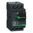
TeSys Deca contactor, 3 poles (3NO), for motor control applications up to 18A/690V AC-3/3e (7.5kW@400V). It provides a 110V 50/60Hz AC coil, 1NO+1NC built-in auxiliary contacts (NC mirror certified), connection by screw clamp terminals. For operating rates until 3600 cycles/hour and environments until 60°C, it procures high reliability and durability. Compact (45mm width), DIN-rail mounting or screw fixing. Multi standards certified (IEC, UL, CSA, CCC, EAC, Marine), Green Premium compliant (RoHS/REACh).
| Range of product | TeSys Deca |
|---|---|
| Product or component type | Contactor |
| Device short name | LC1D |
| Contactor application | Motor control Resistive load |
| Utilisation category | AC-1 AC-4 AC-3 AC-3e |
| Poles description | 3P |
| [Ue] rated operational voltage | Power circuit: <= 690 V AC 25...400 Hz Power circuit: <= 300 V DC |
| [Ie] rated operational current | 18 A (at <60 °C) at <= 440 V AC AC-3 for power circuit 32 A (at <60 °C) at <= 440 V AC AC-1 for power circuit 18 A (at <60 °C) at <= 440 V AC AC-3e for power circuit |
| [Uc] control circuit voltage | 110 V AC 50/60 Hz |
| Motor power kW | 4 kW at 220...230 V AC 50/60 Hz (AC-3) 7.5 kW at 380...400 V AC 50/60 Hz (AC-3) 9 kW at 415...440 V AC 50/60 Hz (AC-3) 10 kW at 500 V AC 50/60 Hz (AC-3) 10 kW at 660...690 V AC 50/60 Hz (AC-3) 4 kW at 400 V AC 50/60 Hz (AC-4) 4 kW at 220...230 V AC 50/60 Hz (AC-3e) 7.5 kW at 380...400 V AC 50/60 Hz (AC-3e) 9 kW at 415...440 V AC 50/60 Hz (AC-3e) 10 kW at 500 V AC 50/60 Hz (AC-3e) 10 kW at 660...690 V AC 50/60 Hz (AC-3e) |
|---|---|
| Motor power hp | 1 hp at 115 V AC 50/60 Hz for 1 phase motors 3 hp at 230/240 V AC 50/60 Hz for 1 phase motors 5 hp at 200/208 V AC 50/60 Hz for 3 phases motors 5 hp at 230/240 V AC 50/60 Hz for 3 phases motors 10 hp at 460/480 V AC 50/60 Hz for 3 phases motors 15 hp at 575/600 V AC 50/60 Hz for 3 phases motors |
| Compatibility code | LC1D |
| Pole contact composition | 3 NO |
| Protective cover | With |
| [Ith] conventional free air thermal current | 10 A (at 60 °C) for signalling circuit 32 A (at 60 °C) for power circuit |
| Irms rated making capacity | 140 A AC for signalling circuit conforming to IEC 60947-5-1 250 A DC for signalling circuit conforming to IEC 60947-5-1 300 A at 440 V for power circuit conforming to IEC 60947 |
| Rated breaking capacity | 300 A at 440 V for power circuit conforming to IEC 60947 |
| [Icw] rated short-time withstand current | 145 A 40 °C - 10 s for power circuit 240 A 40 °C - 1 s for power circuit 40 A 40 °C - 10 min for power circuit 84 A 40 °C - 1 min for power circuit 100 A - 1 s for signalling circuit 120 A - 500 ms for signalling circuit 140 A - 100 ms for signalling circuit |
| Associated fuse rating | 10 A gG for signalling circuit conforming to IEC 60947-5-1 50 A gG at <= 690 V coordination type 1 for power circuit 35 A gG at <= 690 V coordination type 2 for power circuit |
| Average impedance | 2.5 mOhm - Ith 32 A 50 Hz for power circuit |
| Power dissipation per pole | 2.5 W AC-1 0.8 W AC-3 0.8 W AC-3e |
| [Ui] rated insulation voltage | Power circuit: 690 V conforming to IEC 60947-4-1 Power circuit: 600 V CSA certified Power circuit: 600 V UL certified Signalling circuit: 690 V conforming to IEC 60947-1 Signalling circuit: 600 V CSA certified Signalling circuit: 600 V UL certified |
| Overvoltage category | III |
| Pollution degree | 3 |
| [Uimp] rated impulse withstand voltage | 6 kV conforming to IEC 60947 |
| Safety reliability level | B10d = 1369863 cycles contactor with nominal load conforming to EN/ISO 13849-1 B10d = 20000000 cycles contactor with mechanical load conforming to EN/ISO 13849-1 |
| Mechanical durability | 15 Mcycles |
| Electrical durability | 1.65 Mcycles 18 A AC-3 at Ue <= 440 V 1 Mcycles 32 A AC-1 at Ue <= 440 V 1.65 Mcycles 18 A AC-3e at Ue <= 440 V |
| Control circuit type | AC at 50/60 Hz standard |
| Coil technology | Without built-in suppressor module |
| Control circuit voltage limits | 0.3...0.6 Uc (-40…70 °C):drop-out AC 50/60 Hz 0.8...1.1 Uc (-40…60 °C):operational AC 50 Hz 0.85...1.1 Uc (-40…60 °C):operational AC 60 Hz 1...1.1 Uc (60…70 °C):operational AC 50/60 Hz |
| Inrush power in VA | 70 VA 60 Hz cos phi 0.75 (at 20 °C) 70 VA 50 Hz cos phi 0.75 (at 20 °C) |
| Hold-in power consumption in VA | 7.5 VA 60 Hz cos phi 0.3 (at 20 °C) 7 VA 50 Hz cos phi 0.3 (at 20 °C) |
| Heat dissipation | 2…3 W at 50/60 Hz |
| Operating time | 12...22 ms closing 4...19 ms opening |
| Maximum operating rate | 3600 cyc/h at 60 °C |
| Connections - terminals | Control circuit: screw clamp terminals 1 1…4 mm² - cable stiffness: flexible without cable end Control circuit: screw clamp terminals 2 1…4 mm² - cable stiffness: flexible without cable end Control circuit: screw clamp terminals 1 1…4 mm² - cable stiffness: flexible with cable end Control circuit: screw clamp terminals 2 1…2.5 mm² - cable stiffness: flexible with cable end Control circuit: screw clamp terminals 1 1…4 mm² - cable stiffness: solid without cable end Control circuit: screw clamp terminals 2 1…4 mm² - cable stiffness: solid without cable end Power circuit: screw clamp terminals 1 1.5…6 mm² - cable stiffness: flexible without cable end Power circuit: screw clamp terminals 2 1.5…6 mm² - cable stiffness: flexible without cable end Power circuit: screw clamp terminals 1 1…6 mm² - cable stiffness: flexible with cable end Power circuit: screw clamp terminals 2 1…4 mm² - cable stiffness: flexible with cable end Power circuit: screw clamp terminals 1 1.5…6 mm² - cable stiffness: solid without cable end Power circuit: screw clamp terminals 2 1.5…6 mm² - cable stiffness: solid without cable end |
| Tightening torque | Power circuit: 1.7 N.m - on screw clamp terminals - with screwdriver flat Ø 6 mm Power circuit: 1.7 N.m - on screw clamp terminals - with screwdriver Philips No 2 Control circuit: 1.7 N.m - on screw clamp terminals - with screwdriver flat Ø 6 mm Control circuit: 1.7 N.m - on screw clamp terminals - with screwdriver Philips No 2 Control circuit: 1.7 N.m - on screw clamp terminals - with screwdriver pozidriv No 2 Power circuit: 1.7 N.m - on screw clamp terminals - with screwdriver pozidriv No 2 |
| Auxiliary contact composition | 1 NO + 1 NC |
| Auxiliary contacts type | type mechanically linked 1 NO + 1 NC conforming to IEC 60947-5-1 type mirror contact 1 NC conforming to IEC 60947-4-1 |
| Signalling circuit frequency | 25...400 Hz |
| Minimum switching voltage | 17 V for signalling circuit |
| Minimum switching current | 5 mA for signalling circuit |
| Insulation resistance | > 10 MOhm for signalling circuit |
| Non-overlap time | 1.5 ms on de-energisation between NC and NO contact 1.5 ms on energisation between NC and NO contact |
| Mounting support | Plate Rail |
| Standards | CSA C22.2 No 14 EN 60947-4-1 EN 60947-5-1 IEC 60947-4-1 IEC 60947-5-1 UL 60947-4-1 IEC 60335-1:Clause 30.2 IEC 60335-2-40:Annex JJ UL 60335-2-40:Annex JJ CSA C22.2 No 60947-4-1 |
|---|---|
| Product certifications | UL CCC CSA Marine UKCA EAC CB Scheme |
| IP degree of protection | IP20 front face conforming to IEC 60529 |
| Protective treatment | TH conforming to IEC 60068-2-30 |
| Climatic withstand | conforming to IACS E10 exposure to damp heat conforming to IEC 60947-1 Annex Q category D exposure to damp heat |
| Permissible ambient air temperature around the device | -40…60 °C 60…70 °C with derating |
| Operating altitude | 0...3000 m |
| Fire resistance | 850 °C conforming to IEC 60695-2-1 |
| Flame retardance | V1 conforming to UL 94 |
| Mechanical robustness | Vibrations contactor open (2 Gn, 5...300 Hz) Vibrations contactor closed (4 Gn, 5...300 Hz) Shocks contactor open (10 Gn for 11 ms) Shocks contactor closed (15 Gn for 11 ms) |
| Height | 77 mm |
| Width | 45 mm |
| Depth | 86 mm |
| Net weight | 0.33 kg |
| Unit Type of Package 1 | PCE |
|---|---|
| Number of Units in Package 1 | 1 |
| Package 1 Height | 5.2 cm |
| Package 1 Width | 9.2 cm |
| Package 1 Length | 11.2 cm |
| Package 1 Weight | 356.0 g |
| Unit Type of Package 2 | S02 |
| Number of Units in Package 2 | 20 |
| Package 2 Height | 15.0 cm |
| Package 2 Width | 30.0 cm |
| Package 2 Length | 40.0 cm |
| Package 2 Weight | 7.52 kg |
| Unit Type of Package 3 | P06 |
| Number of Units in Package 3 | 320 |
| Package 3 Height | 80.0 cm |
| Package 3 Width | 80.0 cm |
| Package 3 Length | 60.0 cm |
| Package 3 Weight | 129.3 kg |
| Warranty | 18 months |
|---|
Schneider Electric aims to achieve Net Zero status by 2050 through supply chain partnerships, lower impact materials, and circularity via our ongoing “Use Better, Use Longer, Use Again” campaign to extend product lifetimes and recyclability.
Total lifecycle Carbon footprint
21
Environmental Disclosure
Use Better
Packaging made with recycled cardboard
Yes
Packaging without single use plastic
Yes
Compliant
REACh Regulation
PVC free
Yes
Use Again
End of life manual availability
Take-back
No
WEEE Label
The product must be disposed on European Union markets following specific waste collection and never end up in rubbish bins
Dimensions

(1)
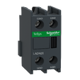
Including LAD 4BB
(2)
Minimum electrical clearance
LC1 | D09…D18 | D093…D123 | D099…D129 | |
|---|---|---|---|---|
b | without add-on blocks | 77 | 99 | 80 |
b1 | with LAD 4BB | 94 | 107 | 95.5 |
with LA4 D●2 | 110(1) | 123(1) | 111.5(1) | |
with LA4 DF, DT | 119(1) | 132(1) | 120.5(1) | |
with LA4 DW, DL | 126(1) | 139(1) | 127.5(1) | |
c | without cover or add-on blocks | 84 | 84 | 84 |
with cover, without add-on blocks | 86 | 86 | 86 | |
c1 | with LAD N or C (2 or 4 contacts) | 117 | 117 | 117 |
c2 | with LA6 DK10, LAD 6K10 | 129 | 129 | 129 |
c3 | with LAD T, R, S | 137 | 137 | 137 |
with LAD T, R, S and sealing cover | 141 | 141 | 141 | |
(1) | Including LAD 4BB. | |||
Wiring

Items usually bought together


Need more information? Check our technical FAQs!
Easily find answers to the most frequently asked questions.