
Roll over image to zoom in


1 videos
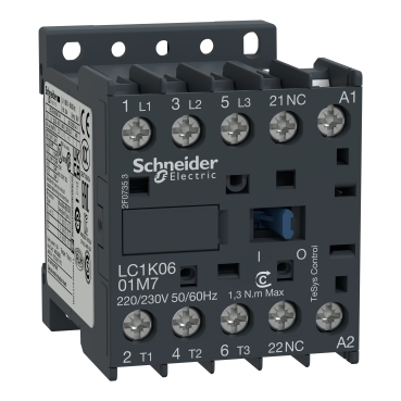
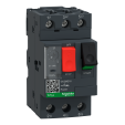
LC1K1201E7
TeSys K is a compact contactor range with a wide variety of coil voltage and terminal connection options
The range delivers strong performance for its compact size and promises seamless integration in all applications
Improved fire resistance with IEC 60335-1(Clause 30.2) certificate by authorized agency
Anti-flammable refrigerants with IEC/EN/UL 60335-2-40(Annex JJ) certificate by authorized agency
The offer features specific versions for railway(TeSys S207)
Environmental Data
Total lifecycle Carbon footprint
59
Use Better
Packaging made with recycled cardboard
Yes
Use Again
Take-back
No


TeSys K contactor, 3 poles (3NO), for motor control applications up to 12A/690V AC-3 (5.5kW@400V), and for non-inductive load control applications up to 20A/690V AC-1. It provides a 48V 50/60Hz AC coil, 1NC built-in auxiliary contact, connection by screw clamp terminals. For operating rates until 600 cycles/hour and environments until 50°C, it procures reliability and durability to standard applications. Very compact (45mm width), DIN-rail mounting or screw fixing. Multi standards certified (IEC, UL, CSA, CCC, EAC), Green Premium compliant (RoHS/REACh).
| Range | TeSys |
|---|---|
| Product or component type | Contactor |
| Device short name | LC1K |
| Device application | Control |
| Contactor application | Motor control Resistive load |
| Utilisation category | AC-3 AC-3e AC-1 AC-4 |
|---|---|
| Poles description | 3P |
| power pole contact composition | 3 NO |
| [Ue] rated operational voltage | Power circuit: <= 690 V AC <= 400 Hz Signalling circuit: <= 690 V AC <= 400 Hz |
| [Ie] rated operational current | 12 A (at <60 °C) at <= 440 V AC AC-3 for power circuit 12 A (at <60 °C) at <= 440 V AC AC-3e for power circuit 20 A (at <60 °C) at <= 690 V AC AC-1 for power circuit |
| Control circuit type | AC at 50/60 Hz |
| [Uc] control circuit voltage | 48 V AC 50/60 Hz |
| Motor power kW | 3 kW at 220...230 V AC 50/60 Hz AC-3 5.5 kW at 380...415 V AC 50/60 Hz AC-3 5.5 kW at 440 V AC 50/60 Hz AC-3 4 kW at 690 V AC 50/60 Hz AC-3 3 kW at 220...230 V AC 50/60 Hz AC-3e 5.5 kW at 380...415 V AC 50/60 Hz AC-3e 5.5 kW at 440 V AC 50/60 Hz AC-3e 4 kW at 690 V AC 50/60 Hz AC-3e 3 kW at 220...230 V AC 50/60 Hz AC-4 5.5 kW at 380...415 V AC 50/60 Hz AC-4 5.5 kW at 440 V AC 50/60 Hz AC-4 4 kW at 690 V AC 50/60 Hz AC-4 |
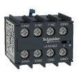
| Auxiliary contact composition | 1 NC |
| [Uimp] rated impulse withstand voltage | 8 kV |
| Overvoltage category | III |
| [Ith] conventional free air thermal current | 20 A (at 60 °C) for power circuit 10 A (at 50 °C) for signalling circuit |
| Irms rated making capacity | 144 A AC for power circuit conforming to IEC 60947 110 A AC for signalling circuit conforming to IEC 60947 |
| Rated breaking capacity | 110 A at 440 V conforming to IEC 60947 80 A at 500 V conforming to IEC 60947 70 A at 660...690 V conforming to IEC 60947 |
| [Icw] rated short-time withstand current | 115 A 50 °C - 1 s for power circuit 105 A 50 °C - 5 s for power circuit 100 A 50 °C - 10 s for power circuit 75 A 50 °C - 30 s for power circuit 55 A 50 °C - 1 min for power circuit 50 A 50 °C - 3 min for power circuit 25 A 50 °C - >= 15 min for power circuit 80 A - 1 s for signalling circuit 90 A - 500 ms for signalling circuit 110 A - 100 ms for signalling circuit |
| Associated fuse rating | 25 A gG at <= 440 V for power circuit 25 A aM for power circuit 10 A gG for signalling circuit conforming to IEC 60947 10 A gG for signalling circuit conforming to VDE 0660 |
| Average impedance | 3 mOhm - Ith 20 A 50 Hz for power circuit |
| Insulation resistance | > 10 MOhm for signalling circuit |
| Inrush power in VA | 30 VA (at 20 °C) |
| Hold-in power consumption in VA | 4.5 VA (at 20 °C) |
| Heat dissipation | 1.3 W |
| Control circuit voltage limits | Operational: 0.8...1.15 Uc (at <50 °C) Drop-out: >= 0.20 Uc (at <50 °C) |
| Connections - terminals | Screw clamp terminals 1 cable(s) 1.5…4 mm²solid Screw clamp terminals 1 cable(s) 0.75…4 mm²flexible without cable end Screw clamp terminals 1 cable(s) 0.34…2.5 mm²flexible with cable end Screw clamp terminals 2 cable(s) 1.5…4 mm²solid Screw clamp terminals 2 cable(s) 0.75…4 mm²flexible without cable end Screw clamp terminals 2 cable(s) 0.34…1.5 mm²flexible with cable end |
| Maximum operating rate | 3600 cyc/h |
| Auxiliary contacts type | type instantaneous 1 NC |
| Signalling circuit frequency | <= 400 Hz |
| Minimum switching current | 5 mA for signalling circuit |
| Minimum switching voltage | 17 V for signalling circuit |
| Operating time | 10...20 ms coil de-energisation and NO opening 10...20 ms coil energisation and NO closing |
| Safety reliability level | B10d = 1369863 cycles contactor with nominal load conforming to EN/ISO 13849-1 B10d = 20000000 cycles contactor with mechanical load conforming to EN/ISO 13849-1 |
| Non overlap distance | 0.5 mm |
| Mechanical durability | 10 Mcycles |
| Electrical durability | 1.3 Mcycles 12 A AC-3 at Ue <= 440 V 1.3 Mcycles 12 A AC-3e at Ue <= 440 V 0.3 Mcycles 20 A AC-1 at Ue <= 690 V 0.02 Mcycles 72 A AC-4 at Ue <= 440 V |
| Mechanical robustness | Shocks contactor closed, on X axis: 10 Gn for 11 ms conforming to IEC 60068-2-27 Shocks contactor closed, on Y axis: 15 Gn for 11 ms conforming to IEC 60068-2-27 Shocks contactor closed, on Z axis: 15 Gn for 11 ms conforming to IEC 60068-2-27 Shocks contactor opened, on X axis: 6 Gn for 11 ms conforming to IEC 60068-2-27 Shocks contactor opened, on Y axis: 10 Gn for 11 ms conforming to IEC 60068-2-27 Shocks contactor opened, on Z axis: 10 Gn for 11 ms conforming to IEC 60068-2-27 Vibrations contactor closed: 4 Gn, 5...300 Hz conforming to IEC 60068-2-6 Vibrations contactor opened: 2 Gn, 5...300 Hz conforming to IEC 60068-2-6 |
| Height | 58 mm |
| Width | 45 mm |
| Depth | 57 mm |
| Standards | EN/IEC 60947-4-1 GB/T 14048.4 UL 60947-4-1 CSA C22.2 No 60947-4-1 JIS C8201-4-1 IEC 60335-1:Clause 30.2 IEC 60335-2-40:Annex JJ UL 60335-2-40:Annex JJ |
|---|---|
| Product certifications | CB Scheme CCC UL CSA EAC CE UKCA |
| Protective treatment | TC conforming to IEC 60068 TC conforming to DIN 50016 |
| Operating altitude | 2000 m without derating |
| Flame retardance | V1 conforming to UL 94 Requirement 2 conforming to NF F 16-101 Requirement 2 conforming to NF F 16-102 |
| Unit Type of Package 1 | PCE |
|---|---|
| Number of Units in Package 1 | 1 |
| Package 1 Height | 6.600 cm |
| Package 1 Width | 4.800 cm |
| Package 1 Length | 6.200 cm |
| Package 1 Weight | 180.000 g |
| Unit Type of Package 2 | S02 |
| Number of Units in Package 2 | 50 |
| Package 2 Height | 15.000 cm |
| Package 2 Width | 30.000 cm |
| Package 2 Length | 40.000 cm |
| Package 2 Weight | 9.320 kg |
| Warranty | 18 months |
|---|
Schneider Electric aims to achieve Net Zero status by 2050 through supply chain partnerships, lower impact materials, and circularity via our ongoing “Use Better, Use Longer, Use Again” campaign to extend product lifetimes and recyclability.
Total lifecycle Carbon footprint
59
Environmental Disclosure
Use Better
Packaging made with recycled cardboard
Yes
Packaging without single use plastic
Yes
Compliant
REACh Regulation
Use Again
End of life manual availability
Take-back
No
WEEE Label
The product must be disposed on European Union markets following specific waste collection and never end up in rubbish bins
Items usually bought together

Need more information? Check our technical FAQs!
Easily find answers to the most frequently asked questions.