
Roll over image to zoom in


1 videos
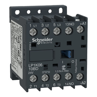
LP1K0610BDTQ
Environmental Data
Total lifecycle Carbon footprint
111
Use Better
Packaging made with recycled cardboard
Yes
Use Again
Recyclability potential, in %
64
Take-back
No


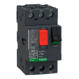
TeSys K contactor, 3 poles (3NO), for motor control applications up to 6A/690V AC-3 (2.2kW@400V). It provides a 24V DC coil, 1NO built-in auxiliary contact, connection by screw clamp terminals. For operating rates until 600 cycles/hour and environments until 50°C, it procures reliability and durability to standard applications. Very compact (45mm width), DIN-rail mounting or screw fixing. Pack of 30 units. Multi standards certified (IEC, UL, CSA, CCC, EAC), Green Premium compliant (RoHS/REACh).
| Range | TeSys |
|---|---|
| Product or component type | Contactor |
| Device short name | LP1K |
| Contactor application | Motor control |
| Utilisation category | AC-3 AC-3e AC-4 |
|---|---|
| Poles description | 3P |
| power pole contact composition | 3 NO |
| [Ue] rated operational voltage | Power circuit: <= 690 V AC <= 400 Hz Signalling circuit: <= 690 V AC <= 400 Hz |
| [Ie] rated operational current | 6 A (at <60 °C) at <= 440 V AC AC-3 for power circuit 6 A (at <60 °C) at <= 440 V AC AC-3e for power circuit |
| Control circuit type | DC standard |
| [Uc] control circuit voltage | 24 V DC |
| Motor power kW | 1.5 kW at 220...230 V AC 50/60 Hz AC-3 2.2 kW at 380...415 V AC 50/60 Hz AC-3 3 kW at 440/690 V AC 50/60 Hz AC-3 1.5 kW at 220...230 V AC 50/60 Hz AC-3e 2.2 kW at 380...415 V AC 50/60 Hz AC-3e 3 kW at 440/690 V AC 50/60 Hz AC-3e 1.5 kW at 220...230 V AC 50/60 Hz AC-4 2.2 kW at 380...415 V AC 50/60 Hz AC-4 3 kW at 440/690 V AC 50/60 Hz AC-4 |
| Auxiliary contact composition | 1 NO |
| [Uimp] rated impulse withstand voltage | 8 kV |
| [Ith] conventional free air thermal current | 20 A (at 60 °C) for power circuit 10 A (at 50 °C) for signalling circuit |
| Irms rated making capacity | 110 A AC for power circuit conforming to IEC 60947 110 A AC for signalling circuit conforming to IEC 60947 |
| Rated breaking capacity | 110 A at 220...230 V conforming to IEC 60947 110 A at 380...400 V conforming to IEC 60947 110 A at 415 V conforming to IEC 60947 110 A at 440 V conforming to IEC 60947 80 A at 500 V conforming to IEC 60947 70 A at 660...690 V conforming to IEC 60947 |
| [Icw] rated short-time withstand current | 90 A 50 °C - 1 s for power circuit 85 A 50 °C - 5 s for power circuit 80 A 50 °C - 10 s for power circuit 60 A 50 °C - 30 s for power circuit 45 A 50 °C - 1 min for power circuit 40 A 50 °C - 3 min for power circuit 20 A 50 °C - >= 15 min for power circuit 80 A - 1 s for signalling circuit 90 A - 500 ms for signalling circuit 110 A - 100 ms for signalling circuit |
| Associated fuse rating | 10 A gG for control circuit conforming to IEC 60947 10 A gG for control circuit conforming to VDE 0660 25 A gG at <= 440 V for power circuit |
| Average impedance | 3 mOhm - Ith 20 A 50 Hz for power circuit |
| [Ui] rated insulation voltage | Control circuit: 690 V conforming to BS 5424 Control circuit: 690 V conforming to IEC 60947 Power circuit: 690 V conforming to BS 5424 Power circuit: 690 V conforming to IEC 60947 Power circuit: 690 V conforming to NF C 20-040 Control circuit: 750 V conforming to VDE 0110 group C Power circuit: 750 V conforming to VDE 0110 group C Control circuit: 600 V conforming to CSA C22.2 No 14 Power circuit: 600 V UL 508 certified conforming to CSA C22.2 No 14 |
| Insulation resistance | > 10 MOhm for control circuit |
| Inrush power in W | 3 W (at 20 °C) |
| Hold-in power consumption in W | 3 W at 20 °C |
| Heat dissipation | 1.3 W |
| Control circuit voltage limits | Operational: 0.8...1.15 Uc (at <50 °C) Drop-out: >= 0.10 Uc (at <50 °C) |
| Connections - terminals | Screw clamp terminals 1 cable(s) 1.5…4 mm²solid Screw clamp terminals 1 cable(s) 0.75…4 mm²flexible without cable end Screw clamp terminals 1 cable(s) 0.34…2.5 mm²flexible with cable end Screw clamp terminals 2 cable(s) 1.5…4 mm²solid Screw clamp terminals 2 cable(s) 0.75…4 mm²flexible without cable end Screw clamp terminals 2 cable(s) 0.34…1.5 mm²flexible with cable end Power circuit: screw clamp terminals 2 cable(s) 1.5 mm²flexible with cable end Power circuit: spring terminals 1 cable(s) 0.75 mm²solid Power circuit: spring terminals 1 cable(s) 1.5 mm²solid Power circuit: spring terminals 1 cable(s) 0.75 mm²flexible Power circuit: spring terminals 1 cable(s) 1.5 mm²flexible Control circuit: spring terminals 1 cable(s) 0.75 mm²solid Control circuit: spring terminals 1 cable(s) 1.5 mm²solid Control circuit: spring terminals 1 cable(s) 0.75 mm²flexible Control circuit: spring terminals 1 cable(s) 1.5 mm²flexible |
| Maximum operating rate | 3600 cyc/h |
| Coil technology | Without built-in bidirectional peak limiting diode suppressor |
| Minimum switching current | 5 mA for control circuit |
| Minimum switching voltage | 17 V for control circuit |
| Mounting support | Plate Rail |
| Tightening torque | Power circuit: 0.8…1.3 N.m - on screw clamp terminal flat Ø 6 mm Power circuit: 0.8…1.3 N.m - on screw clamp terminal Philips No 2 Power circuit: 0.8…1.3 N.m - on screw clamp terminals pozidriv No 2 |
| Operating time | 10 ms coil de-energisation and NO opening 15 ms coil de-energisation and NC opening 25...35 ms coil energisation and NC opening 30...40 ms between energisation of coil and closing of NO contact |
| Safety reliability level | B10d = 1369863 cycles contactor with nominal load conforming to EN/ISO 13849-1 B10d = 20000000 cycles contactor with mechanical load conforming to EN/ISO 13849-1 |
| Mechanical durability | 10 Mcycles |
| Electrical durability | 1.3 Mcycles 6 A AC-3 at Ue <= 440 V 1.3 Mcycles 6 A AC-3e at Ue <= 440 V 0.05 Mcycles 36 A AC-4 at Ue <= 440 V |
| Height | 58 mm |
| Width | 45 mm |
| Depth | 57 mm |
| Net weight | 0.225 kg |
| Standards | EN/IEC 60947-4-1 EN/IEC 60947-5-1 UL 60947-4-1 UL 60947-5-1 CSA C22.2 No 60947-4-1 CSA C22.2 No 60947-5-1 GB/T 14048.4 |
|---|---|
| Product certifications | CB Scheme CCC UL CSA EAC CE UKCA |
| IP degree of protection | IP2X |
| Protective treatment | TC conforming to IEC 60068 |
| Ambient air temperature for operation | -25…50 °C |
| Ambient air temperature for storage | -50…80 °C |
| Operating altitude | 2000 m without derating |
| Fire resistance | 850 °C conforming to IEC 60695-2-1 |
| Flame retardance | Class C2 conforming to NF F 16-101 Class C2 conforming to NF F 16-102 V1 conforming to UL 94 |
| Unit Type of Package 1 | PCE |
|---|---|
| Number of Units in Package 1 | 1 |
| Package 1 Height | 6.000 cm |
| Package 1 Width | 4.500 cm |
| Package 1 Length | 5.000 cm |
| Package 1 Weight | 200.000 g |
| Unit Type of Package 2 | CAR |
| Number of Units in Package 2 | 30 |
| Package 2 Height | 6.500 cm |
| Package 2 Width | 29.500 cm |
| Package 2 Length | 29.500 cm |
| Package 2 Weight | 6.450 kg |
| Warranty | 18 months |
|---|
Schneider Electric aims to achieve Net Zero status by 2050 through supply chain partnerships, lower impact materials, and circularity via our ongoing “Use Better, Use Longer, Use Again” campaign to extend product lifetimes and recyclability.
Total lifecycle Carbon footprint
111
Environmental Disclosure
Use Better
Packaging made with recycled cardboard
Yes
Packaging without single use plastic
Yes
Compliant
REACh Regulation
Use Again
Recyclability potential, in %
64
End of life manual availability
Take-back
No
WEEE Label
The product must be disposed on European Union markets following specific waste collection and never end up in rubbish bins
Items usually bought together


Need more information? Check our technical FAQs!
Easily find answers to the most frequently asked questions.