

Roll over image to zoom in


1 videos
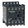
LR7K0310
Easy to separate or direct mounting of OLR with CTR, save installation and assembly of panel components
selection of reset mode: Manual (marked H) or Automatic (marked A),
with relay trip indicator to facilitate motor status monitoring
Widely used for industry, infrastructure and building applications.
Designed for simple control systems
Environmental Data
Total lifecycle Carbon footprint
6
Use Better
Packaging made with recycled cardboard
Yes
Use Again
Take-back
No

TeSys LRK thermal overload relay, thermal setting range 2.6-3.7A, tripping class 10A, for protection of 3-phase motors. Non differential device, it can be used with unbalanced loads. It provides a thermal adjustement dial, a manual-automatic reset selector, a test selector for simulation of a tripping, reset and stop buttons, a flag indicator and 2 auxiliary contacts 1NO+1NC for fault signalling. Settings are protected by a transparent cover lockable by sealing. Connection by screw clamp terminals, it connects directly to the bottom terminals of TeSys K series contactors. Mounting on DIN rail or screw fixing, separated from the contactor, with using terminal block LA7K0064 (to be ordered separately).
| Range | TeSys |
|---|---|
| Product name | TeSys LRK |
| Product or component type | Non differential thermal overload relay |
| Device short name | LR7K |
| Relay application | Motor protection |
| Product compatibility | LC1K LP4K LC7K LP1K |
| Network type | AC DC |
| Thermal overload class | Class 10A conforming to IEC 60947-4-1 |
| Thermal protection adjustment range | 2.6…3.7 A |
| [Ui] rated insulation voltage | Power circuit: 690 V conforming to BS 4941 Power circuit: 690 V conforming to IEC 60947 Power circuit: 750 V conforming to VDE 0110 group C Power circuit: 600 V conforming to CSA C22.2 No 14 |
| Network frequency | <= 400 Hz |
|---|---|
| Mounting support | Under contactor Plate, with specific accessories Rail, with specific accessories |
| Auxiliary contact composition | 1 NO + 1 NC |
| [Ith] conventional free air thermal current | 6 A for signalling circuit |
| [Ue] rated operational voltage | <= 690 V for power circuit 690 V AC AC-15 for signalling circuit 250 V DC DC-13 for signalling circuit |
| Associated fuse rating | 6 A gG for signalling circuit conforming to VDE 0660 6 A gG for signalling circuit conforming to IEC 60947 |
| [Uimp] rated impulse withstand voltage | 6 kV |
| Power dissipation per pole | 2 W |
| Local signalling | Trip indicator (yellow) |
| Control type | Red push-button: trip test function Blue push-button: stop and manual reset selector switch: manual or automatic reset |
| Connections - terminals | Screw clamp terminals 1 cable(s) 1.5…4 mm²solid Screw clamp terminals 2 cable(s) 1.5…4 mm²solid Screw clamp terminals 1 cable(s) 0.75…4 mm²flexible without cable end Screw clamp terminals 2 cable(s) 0.75…4 mm²flexible without cable end Screw clamp terminals 1 cable(s) 0.34…2.5 mm²flexible with cable end Screw clamp terminals 2 cable(s) 0.34…1.5 mm²flexible with cable end |
| Tightening torque | 1.3 N.m - on screw clamp terminals - with screwdriver Philips No 2 1.3 N.m - on screw clamp terminals - with screwdriver flat Ø 6 mm 1.3 N.m - on screw clamp terminals - with screwdriver pozidriv No 2 |
| Height | 58 mm |
| Width | 45 mm |
| Depth | 65 mm |
| Net weight | 0.145 kg |
| Standards | BS 4941 IEC 60947 VDE 0660 NF C 63-650 |
|---|---|
| Product certifications | UL CSA UKCA |
| Protective treatment | TC conforming to IEC 60068 TC conforming to DIN 50016 |
| IP degree of protection | IP2X conforming to IEC 60529 |
| Ambient air temperature for operation | -20…55 °C without derating conforming to IEC 60947 -30…60 °C with derating conforming to IEC 60947 |
| Ambient air temperature for storage | -40…70 °C |
| Operating altitude | 2000 m without derating |
| Fire resistance | 850 °C conforming to IEC 60695-2-1 |
| Flame retardance | V1 conforming to UL 94 Requirement 2 conforming to NF F 16-101 Requirement 2 conforming to NF F 16-102 |
| Mechanical robustness | Shocks NO contact: 10 Gn for 11 ms conforming to IEC 60068-2-27 Shocks NC contact: 10 Gn for 11 ms conforming to IEC 60068-2-27 Vibrations NO contact: 2 Gn, 5...300 Hz conforming to IEC 60068-2-6 Vibrations NC contact: 2 Gn, 5...300 Hz conforming to IEC 60068-2-6 |
| Unit Type of Package 1 | PCE |
|---|---|
| Number of Units in Package 1 | 1 |
| Package 1 Height | 7.200 cm |
| Package 1 Width | 4.800 cm |
| Package 1 Length | 8.500 cm |
| Package 1 Weight | 154.000 g |
| Unit Type of Package 2 | S02 |
| Number of Units in Package 2 | 41 |
| Package 2 Height | 15.000 cm |
| Package 2 Width | 30.000 cm |
| Package 2 Length | 40.000 cm |
| Package 2 Weight | 6.574 kg |
| Unit Type of Package 3 | P06 |
| Number of Units in Package 3 | 656 |
| Package 3 Height | 75.000 cm |
| Package 3 Width | 80.000 cm |
| Package 3 Length | 60.000 cm |
| Package 3 Weight | 113.184 kg |
| Warranty | 18 months |
|---|
Schneider Electric aims to achieve Net Zero status by 2050 through supply chain partnerships, lower impact materials, and circularity via our ongoing “Use Better, Use Longer, Use Again” campaign to extend product lifetimes and recyclability.
Total lifecycle Carbon footprint
6
Environmental Disclosure
Use Better
Packaging made with recycled cardboard
Yes
Packaging without single use plastic
Yes
Compliant
SCIP Number
E145d1bc-6ab6-4bb3-beeb-cb7d7952e3f6
REACh Regulation
Use Again
End of life manual availability
Take-back
No
WEEE Label
The product must be disposed on European Union markets following specific waste collection and never end up in rubbish bins
Items usually bought together


Need more information? Check our technical FAQs!
Easily find answers to the most frequently asked questions.