
Roll over image to zoom in


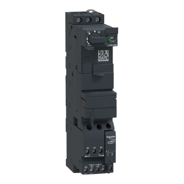
LU2B12BL
DIN-rail mounting and screw fixing
Type of control to be acheived: Basic or Advanced.
Modular, plug & play structure helps you to perform quick maintenance
Direct access to detailed information for every motor starter of your installation
Advanced motor management system
Environmental Data
Total lifecycle Carbon footprint
23
Use Better
Packaging made with recycled cardboard
Yes
Use Again
Take-back
No


TeSys U standard reversing power base, 3 poles (3NO), rated 12A/690V, to be completed with a control unit LUC to form a TeSys U reversing starter controller, for 3-phase motor applications up to 5.5kW@400V. Base composed of power contacts, control coil, rotary handle, with a modular design for additional modules to form a "all in one" reversing starter controller with basic or advanced protection and control functions. It is equipped with a reverser module LU2MB0BL to be supplied with 24V DC, auxiliary signaling contacts (1NO+1NC), a control terminal block, blanking shutters covering the empty cavities. It provides a high breaking capacity Icu 50kA@400V, start-stop control guaranteed for 3600 cycles/hour. Very compact (45mm width), DIN-rail mounting and screw fixing, with a padlockable rotary handle. Certified when used in conjunction with a LUC control unit (IEC, UL, CSA, CCC, EAC, Marine), Green Premium compliant (RoHS/REACh).
| Range | TeSys |
|---|---|
| Product name | TeSys Ultra |
| Device short name | LU2B |
| Product or component type | Reversing power base |
| Device application | Motor control Motor protection |
| Product compatibility | Control unit LUC.X6BL Control unit LUC.1XBL Control unit LUC.05BL Control unit LUC.12BL |
| Poles description | 3P |
| Suitability for isolation | Yes |
| [Ue] rated operational voltage | 690 V AC for power circuit |
| Network frequency | 40...60 Hz |
| [Ith] conventional free air thermal current | 12 A |
| [Ie] rated operational current | 12 A at <= 440 V 12 A at 500 V 9 A at 690 V |
| Utilisation category | AC-43 AC-44 AC-41 |
| [Ics] rated service breaking capacity | 50 kA at 230 V 50 kA at 440 V 10 kA at 500 V 4 kA at 690 V |
| Auxiliary contact composition | 1 NO + 1 NC |
| Auxiliary contacts type | type linked contacts (1 NO + 1 NC) conforming to IEC 60947-4-1 type mirror contact (1 NC) conforming to IEC 60947-1 |
| [Uc] control circuit voltage | 24 V DC |
| Control circuit voltage limits | 14.5 V DC drop-out 20...27 V DC in operation |
| Typical current consumption | 120 mA at 24 V DC I maximum while closing 120 mA at 24 V DC I rms sealed |
|---|---|
| Heat dissipation | 2 W for control circuit with LUCA, LUCB, LUCC, LUCD 1.7 W for control circuit with LUCM |
| Inrush restraint duration | 15 ms DC |
| Safety reliability level | B10d = 1369863 cycles contactor with nominal load conforming to EN/ISO 13849-1 B10d = 20000000 cycles contactor with mechanical load conforming to EN/ISO 13849-1 |
| Operating time | 150 ms with change of direction for power circuit 75 ms without change of direction for power circuit 35 ms opening with LUCA, LUCB, LUCC, LUCD, LUCM for control circuit 75 ms closing with LUCM for control circuit 70 ms closing with LUCA, LUCB, LUCC, LUCD for control circuit |
| Mechanical durability | 15 Mcycles |
| maximum operating rate | 3600 cyc/h |
| Product certifications | CE UL CSA CCC EAC ASEFA ATEX Marine |
| Standards | EN 60947-6-2 IEC 60947-6-2 UL 60947-4-1, with phase barrier CSA C22.2 No 60947-4-1, with phase barrier |
| [Ui] rated insulation voltage | 690 V conforming to IEC 60947-6-2 (pollution degree 3) 600 V conforming to UL 60947-4-1 600 V conforming to CSA C22.2 No 60947-4-1 |
| [Uimp] rated impulse withstand voltage | 6 kV conforming to IEC 60947-6-2 |
| Safe separation of circuit | 400 V SELV between the control and auxiliary circuits conforming to IEC 60947-1 appendix N 400 V SELV between the control or auxiliary circuit and the main circuit conforming to IEC 60947-1 appendix N |
| Fixing mode | Clipped (DIN rail) Screw-fixed (plate) |
| Connections - terminals | Control circuit: screw clamp terminals 1 cable(s) 0.34…1.5 mm² flexible with cable end Control circuit: screw clamp terminals 1 cable(s) 0.75…1.5 mm² flexible without cable end Control circuit: screw clamp terminals 1 cable(s) 0.75…1.5 mm² rigid Control circuit: screw clamp terminals 2 cable(s) 0.34…1.5 mm² flexible with cable end Control circuit: screw clamp terminals 2 cable(s) 0.75…1.5 mm² flexible without cable end Control circuit: screw clamp terminals 2 cable(s) 0.75…1.5 mm² rigid Power circuit: screw clamp terminals 1 cable(s) 1…10 mm² rigid Power circuit: screw clamp terminals 1 cable(s) 1…6 mm² flexible with cable end Power circuit: screw clamp terminals 1 cable(s) 2.5…10 mm² flexible without cable end Power circuit: screw clamp terminals 2 cable(s) 1…6 mm² flexible with cable end Power circuit: screw clamp terminals 2 cable(s) 1…6 mm² rigid Power circuit: screw clamp terminals 2 cable(s) 1.5…6 mm² flexible without cable end |
| Tightening torque | Control circuit: 0.8…1.2 N.m flat screwdriver 5 mm Control circuit: 0.8…1.2 N.m Philips no 1 screwdriver 5 mm Power circuit: 1.9…2.5 N.m flat screwdriver 6 mm Power circuit: 1.9…2.5 N.m Philips No 2 screwdriver 6 mm Power circuit: 1.9…2.5 N.m pozidriv No 2 screwdriver 6 mm |
| Width | 45 mm |
| Height | 224 mm |
| Depth | 126 mm |
| Net weight | 1.27 kg |
| Compatibility code | LU2B |
| IP degree of protection | IP20 conforming to IEC 60947-1 (front panel and wired terminals) IP20 conforming to IEC 60947-1 (other faces) IP40 conforming to IEC 60947-1 (front panel outside connection zone) |
|---|---|
| Protective treatment | TH conforming to IEC 60068 |
| Ambient air temperature for operation | -25…60 °C with LUCM -25…70 °C with LUCA, LUCB, LUCC, LUCD |
| Ambient air temperature for storage | -40…85 °C |
| Fire resistance | 960 °C parts supporting live components conforming to IEC 60695-2-12 650 °C conforming to IEC 60695-2-12 |
| Operating altitude | 2000 m |
| Shock resistance | 10 gn power poles open conforming to IEC 60068-2-27 15 gn power poles closed conforming to IEC 60068-2-27 |
| Vibration resistance | 2 gn (f= 5…300 Hz) power poles open conforming to IEC 60068-2-27 4 gn (f= 5…300 Hz) power poles closed conforming to IEC 60068-2-27 |
| Resistance to electrostatic discharge | 8 kV level 3 in open air conforming to IEC 61000-4-2 8 kV level 4 on contact conforming to IEC 61000-4-2 |
| Resistance to fast transients | 2 kV class 3 serial link conforming to IEC 61000-4-4 4 kV class 4 all circuits except for serial link conforming to IEC 61000-4-4 |
| Resistance to radiated fields | 10 V/m 3 conforming to IEC 61000-4-3 |
| Immunity to radioelectric fields | 10 V conforming to IEC 61000-4-6 |
| Immunity to microbreaks | 3 ms for control circuit |
| Immunity to voltage dips | 70 % / 500 ms conforming to IEC 61000-4-11 |
| Unit Type of Package 1 | PCE |
|---|---|
| Number of Units in Package 1 | 1 |
| Package 1 Height | 25.000 cm |
| Package 1 Width | 5.500 cm |
| Package 1 Length | 14.700 cm |
| Package 1 Weight | 1.292 kg |
| Unit Type of Package 2 | S03 |
| Number of Units in Package 2 | 9 |
| Package 2 Height | 30.000 cm |
| Package 2 Width | 30.000 cm |
| Package 2 Length | 40.000 cm |
| Package 2 Weight | 12.245 kg |
| Unit Type of Package 3 | P06 |
| Number of Units in Package 3 | 72 |
| Package 3 Height | 75.000 cm |
| Package 3 Width | 60.000 cm |
| Package 3 Length | 80.000 cm |
| Package 3 Weight | 110.100 kg |
Schneider Electric aims to achieve Net Zero status by 2050 through supply chain partnerships, lower impact materials, and circularity via our ongoing “Use Better, Use Longer, Use Again” campaign to extend product lifetimes and recyclability.
Total lifecycle Carbon footprint
23
Environmental Disclosure
Use Better
Packaging made with recycled cardboard
Yes
Packaging without single use plastic
Yes
Compliant with Exemptions
SCIP Number
19d2f48a-9308-42e2-8a8a-e2be758e3b3a
REACh Regulation
Halogen-free status
Product contains halogen above thresholds
PVC free
Yes
Use Again
End of life manual availability
Take-back
No
WEEE Label
The product must be disposed on European Union markets following specific waste collection and never end up in rubbish bins
Items usually bought together


Need more information? Check our technical FAQs!
Easily find answers to the most frequently asked questions.