
Roll over image to zoom in

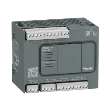
TM200C16R
Designed for simple machines
Easy to test and debug thanks to the standard USport and removable terminal blocks
Easy to duplicate without special skills using the Micro SD memory card
Easy to access information by scanning the QRcode carved on the front of the controller
Monitoring for up to 196 I/O and 2 axis motion control
Environmental Data
Total lifecycle Carbon footprint
4599
Use Better
Packaging made with recycled cardboard
Yes
Use Again
Take-back
No


This product is part of the Easy modicon M200 range, an offer of logic controllers for up to 196 I/O, 2 axis motion control. This logic controller provides 1 regular input, 4 fast inputs, 4 high speed inputs and 7 relay outputs. Its supply voltage is 100VAC to 240VAC. It embedds 1 serial link port (RS 485), and a USB port dedicated to programming. This controller is suitable at an affordable price, without compromising on simplicity, robustness, availability and services. It embeds a PID process control, PTO, PWM and PLS position control. Its voltage limit (ripple included) is 85VAC to 264VAC (50/60Hz). Its maximum consumption stands between 61VAC and 74VAC. Its dimensions are 110mm wide x 70mm deep x 90mm high. It weighs 0.359kg. This logic controller has been specifically designed for textile, machine tool, packaging, HVAC, material handling, pumping, hoisting and machines for electronic assembly applications. This product is certified by CE, CSA, IACS E10, RCM and CULus. It meets EN/IEC 61010-2-201 and EN/IEC 61131-2 standards. This controller is compatible with optional cartridges which offer digital I/O and analog I/O expansions, and Serial Link communication port expansions. It supports DIN rail mount. Easy modicon M200 controllers are entry-level products perfectly suited to meet specific needs of emerging markets at an affordable price without compromise. Easy modicon M200 logic controllers, the best performance/price ratio solutions for your small automation systems requiring flexibility and simple motion.
| Range of product | Easy Modicon M200 |
|---|---|
| Product or component type | Logic controller |
| [Us] rated supply voltage | 100...240 V AC |
| Discrete I/O number | 16 |
| Discrete input number | I8: 1 regular input I2...I5: 4 fast input I0, I1, I6, I7: 4 high speed input |
| Discrete output number | 7 relay |
| Discrete input voltage | 24 V |
| Discrete input voltage type | DC |
| Discrete input current | 7 mA for input |
| Discrete input logic | Sink or source (positive/negative) type 1 conforming to IEC 61131-2 |
| Discrete output voltage | 24 V DC 220 V AC |
| Discrete output current | 2 A |
| Discrete output type | Relay normally open |
| Power consumption in VA | 51…63 VA at 100...240 V AC (with max I/O) |
| Maximum number of I/O expansion module | 4 with 64 discrete output(s) for transistor output 4 with 71 discrete output(s) for relay output |
|---|---|
| Supply voltage limits | 85…264 V |
| Network frequency | 50/60 Hz |
| Inrush current | 50 A |
| Voltage state 1 guaranteed | >= 15 V for input |
| Voltage state 0 guaranteed | <= 5 V for input |
| Input impedance | 3.3 kOhm for discrete input |
| Response time | 10 ms turn-off, Q0...Q6 terminal(s) for relay output 10 ms turn-on, Q0...Q6 terminal(s) for relay output 5 µs turn-off, I0, I1, I6, I7 terminal(s) for high speed input 5 µs turn-on, I0, I1, I6, I7 terminal(s) for high speed input 100 µs turn-off, I2...I5 terminal(s) for fast input 35 µs turn-on, I2...I5 terminal(s) for fast input 100 µs turn-off, I8 terminal(s) for regular input 35 µs turn-on, I8 terminal(s) for regular input |
| Configurable filtering time | 0 ms for input 3 ms for input 12 ms for input |
| Output voltage limits | 30 V DC 250 V AC |
| Maximum current per output common | 4 A at COM 0 4 A at COM 1 |
| Electrical durability | 100000 cycles AC-12, 240 V, 480 VA, resistive 100000 cycles DC-12, 24 V, 48 W, resistive |
| Switching frequency | 0.1 Hz with maximum load |
| Mechanical durability | 20000000 cycles for relay output |
| Minimum load | 10 mA at 5 V DC for relay output |
| Memory capacity | 512 byte internal flash with 10000 instructions for backup of programs |
| Data storage equipment | 32 GB micro SD card (optional) |
| Battery type | BR2032 Li-CFx (Lithium-Carbon Monofluoride), battery life: 5 year(s) |
| Backup time | 3 years at 25 °C (by interruption of power supply) |
| Execution time for 1 KInstruction | 0.3 ms for event and periodic task |
| Execution time per instruction | 0.2 µs Boolean |
| Exct time for event task | 60 µs response time |
| Clock drift | <= 90 s/month at 25 °C |
| Regulation loop | Adjustable PID regulator up to 14 simultaneous loops |
| Control signal type | Quadrature (x1, x2, x4) at 100 kHz for fast input (HSC mode) Pulse/direction at 100 kHz for fast input (HSC mode) Single phase at 100 kHz for fast input (HSC mode) CW/CCW at 100 kHz for fast input (HSC mode) |
| Counting input number | 4 fast input (HSC mode) at 100 kHz 32 bits |
| Integrated connection type | USB port with mini B USB 2.0 connector Non isolated serial link serial 1 with terminal block connector and RS485 interface Non isolated serial link serial 2 with terminal block connector and RS232/RS485 interface Isolated serial link serial 2 with terminal block connector and RS485 interface |
| Transmission rate | 1.2...115.2 kbit/s (115.2 kbit/s by default) for bus length of 15 m for RS485 1.2...115.2 kbit/s (115.2 kbit/s by default) for bus length of 3 m for RS232 12 Mbit/s for USB |
| Communication port protocol | USB port: USB - SoMachine-Network Non isolated serial link: Modbus master/slave - RTU/ASCII or SoMachine-Network |
| Local signalling | 1 LED (green) for PWR 1 LED (green) for RUN 1 LED (red) for module error (ERR) 1 LED (green) for SD card access (SD) 1 LED (red) for BAT 1 LED (green) for SL1 1 LED per channel (green) for I/O state |
| Electrical connection | Mini B USB 2.0 connectorfor a programming terminal removable screw terminal blockfor inputs removable screw terminal blockfor outputs removable screw terminal block, 4 terminal(s) for connecting the serial link1 removable screw terminal block, 3 terminal(s) for connecting the 100-240 V AC power supply |
| Maximum cable distance between devices | Unshielded cable: <50 m for input Shielded cable: <10 m for fast input Shielded cable: <10 m for high speed input Unshielded cable: <150 m for output |
| Insulation | Non-insulated between inputs Between output and internal logic at 1780 V AC Between output groups at 1780 V AC Between supply and internal logic at 1780 V AC Between input and internal logic at 500 V AC Between fast input and internal logic at 500 V AC Between input groups at 500 V AC |
| Sensor power supply | 24 V DC at 250 mA supplied by the controller |
| Marking | CE |
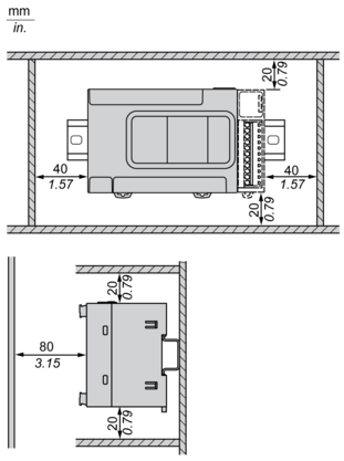
| Mounting support | Top hat type TH35-15 rail conforming to IEC 60715 Top hat type TH35-7.5 plate or panel with fixing kit conforming to IEC 60715 |
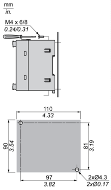
| Height | 90 mm |
| Depth | 70 mm |
| Width | 110 mm |
| Net weight | 0.359 kg |
| IP degree of protection | IP20 with protective cover in place |
|---|---|
| Product certifications | CSA cULus IACS E10 RCM |
| Standards | IEC 61131-2 IEC 61010-2-201 |
| Electromagnetic compatibility | Electrostatic discharge immunity test - test level: 8 kV (air discharge) conforming to IEC 61000-4-2 Electrostatic discharge immunity test - test level: 6 kV (contact discharge) conforming to IEC 61000-4-2 Susceptibility to electromagnetic fields - test level: 10 V/m (80 MHz...3 GHz) conforming to IEC 61000-4-3 Magnetic field at power frequency - test level: 30 A/m conforming to IEC 61000-4-8 Electrical fast transient/burst immunity test - test level: 2 kV (power lines) conforming to IEC 61000-4-4 Electrical fast transient/burst immunity test - test level: 2 kV (relay output) conforming to IEC 61000-4-4 Electrical fast transient/burst immunity test - test level: 1 kV (I/O) conforming to IEC 61000-4-4 Electrical fast transient/burst immunity test - test level: 1 kV (serial link) conforming to IEC 61000-4-4 1.2/50 µs shock waves immunity test - test level: 1 kV (power lines (DC)) conforming to IEC 61000-4-5 1.2/50 µs shock waves immunity test - test level: 2 kV (power lines (AC)) conforming to IEC 61000-4-5 1.2/50 µs shock waves immunity test - test level: 2 kV (relay output) conforming to IEC 61000-4-5 1.2/50 µs shock waves immunity test - test level: 1 kV (I/O) conforming to IEC 61000-4-5 1.2/50 µs shock waves immunity test - test level: 1 kV (shielded cable) conforming to IEC 61000-4-5 1.2/50 µs shock waves immunity test - test level: 0.5 kV (power lines (DC)) conforming to IEC 61000-4-5 1.2/50 µs shock waves immunity test - test level: 1 kV (power lines (AC)) conforming to IEC 61000-4-5 Conducted RF disturbances - test level: 10 V (0.15...80 MHz) conforming to IEC 61000-4-6 Conducted emission - test level: 79 dBμV/m QP/66 dBμV/m AV (power lines (AC)) conforming to IEC 55011 Conducted emission - test level: 73 dBμV/m QP/60 dBμV/m AV (power lines (AC)) conforming to IEC 55011 Radiated emission - test level: 40 dBμV/m QP class A (10 m) conforming to IEC 55011 Radiated emission - test level: 47 dBμV/m QP class A (10 m) conforming to IEC 55011 1.2/50 µs shock waves immunity test - test level: 1 kV (relay output) conforming to IEC 61000-4-5 |
| Shock resistance | 15 gn for 11 ms 30 gn for 6 ms |
| Immunity to microbreaks | 10 ms |
| Vibration resistance | 3.5 mm at 5…8.4 Hz on symmetrical rail 1 gn at 8.4…150 Hz on symmetrical rail 3.5 mm at 5…8.7 Hz on panel mounting 2 gn at 8.7…150 Hz on panel mounting |
| Relative humidity | 10…95 %, without condensation (in operation) 10…95 %, without condensation (in storage) |
| Ambient air temperature for operation | 0…55 °C (horizontal installation) |
| Ambient air temperature for storage | -25…70 °C |
| Pollution degree | <= 2 |
| Operating altitude | 0...2000 m |
| Storage altitude | 0…3000 m |
| Unit Type of Package 1 | PCE |
|---|---|
| Number of Units in Package 1 | 1 |
| Package 1 Height | 9.598 cm |
| Package 1 Width | 12.326 cm |
| Package 1 Length | 13.738 cm |
| Package 1 Weight | 508 g |
| Unit Type of Package 2 | S03 |
| Number of Units in Package 2 | 18 |
| Package 2 Height | 30 cm |
| Package 2 Width | 30 cm |
| Package 2 Length | 40 cm |
| Package 2 Weight | 9744 g |
| Unit Type of Package 3 | P12 |
| Number of Units in Package 3 | 432 |
| Package 3 Height | 95 cm |
| Package 3 Width | 80 cm |
| Package 3 Length | 120 cm |
| Package 3 Weight | 242856 g |
Schneider Electric aims to achieve Net Zero status by 2050 through supply chain partnerships, lower impact materials, and circularity via our ongoing “Use Better, Use Longer, Use Again” campaign to extend product lifetimes and recyclability.
Total lifecycle Carbon footprint
4599
Environmental Disclosure
Use Better
Packaging made with recycled cardboard
Yes
Packaging without single use plastic
Yes
Pro-active compliance (Product out of EU RoHS legal scope)
REACh Regulation
Use Again
End of life manual availability
Take-back
No
Dimensions Drawings
Dimensions

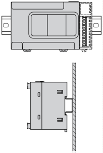
Mounting and Clearance
Mounting on a Rail

Direct Mounting on a Panel Surface
Mounting Position

Clearance
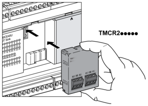
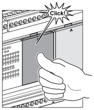
TMCR2•••Installation

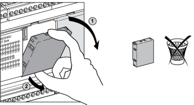

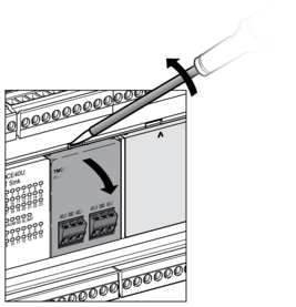
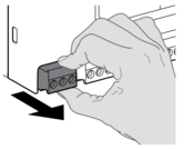
TMCR2••• De-Installation


Wiring Diagram / Connections Schema
AC Power Supply

(*) Type T fuse
Digital Inputs Positive Logic (Sink)

(*) Type T fuse
(**) Fast inputs
Digital Inputs Negative Logic (Source)

(*) Type T fuse
(**) Fast inputs
Relay Outputs - Negative Logic (Sink)

(*) Type T fuse
(1) The COM0 and COM1 terminals are not connected internally.
(2) A free wheeling diode or an RC snubber
Relay Outputs - Positive Logic (Source)

(*) Type T fuse
(1) The COM0 and COM1 terminals are not connected internally.
(2) A free wheeling diode or an RC snubber
USB Mini-B Connection

SL1 Connection
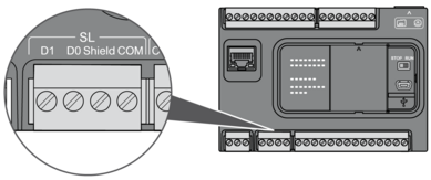
D1 : D1 (A+)
D0 : D0 (B-)
Shield : Shield
COM : O V Com
Derating Curves
Digital Inputs
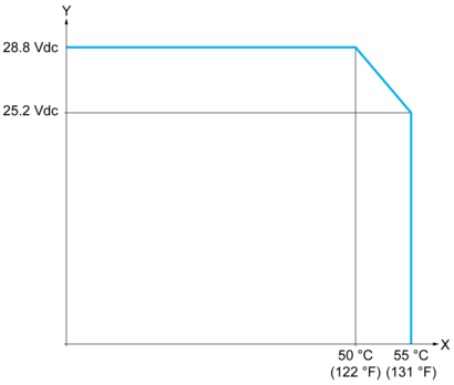
X : Ambient temperature (°C / °F)
Y : Input voltage (V)
Relay Outputs
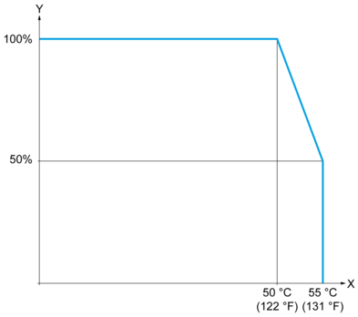
X : Ambient temperature (°C / °F)
Y : Output load current (%)
Need more information? Check our technical FAQs!
Easily find answers to the most frequently asked questions.