
Roll over image to zoom in

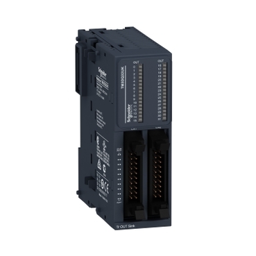
TM3DQ32UK
Expansion I/O modules for Modicon M221, M241, M251 and M262 controllers
Modularity and easness of installation
Large choice of I/O system to enhance the capabilities of Modicon M2xx plc
Intuitive machine programming with EcoStruxure Machine Expert
Modicon TM3 system allows to Modicon M2xx plc flexible and customizable I/O extension
Environmental Data
Total lifecycle Carbon footprint
56
Use Better
Packaging made with recycled cardboard
Yes
Use Again
Take-back
No
Compatible Software

SRVEW1YMSL00
This product is part of the Modicon TM3 range, an offer of expansion I/O modules for Modicon M221, M241, M251 and M262. The discrete output module provides 32 transistor outputs with sink (negative)logic. It is an output module with an output voltage of 24V DC and a current consumption of 40mA at 24V DC via bus connector. This product is capable of controlling variable speed drives or any device equipped with a current or voltage input. There is an insulation between output and internal logic at 500V AC, non-insulated between outputs. It is furnished with HE-10 connector outputs for electrical connection. It is an IP20 rated product. Its dimensions are 33.5mm (Width) x 81.3mm (Depth) x 90mm (Height). It weighs 0.115kg. This product is certified by CE, CULus and C-Tick. It meets EN/IEC 61131-2 and EN/IEC 61010-2-201 standards. This module is compatible with Modicon M262, Modicon M241, Modicon M251 and Modicon M221 logic controller. It supports top hat type TH35-15, top hat type TH35-7.5 rail conforming to IEC 60715 and plate or panel with fixing kit mount. Modicon TM3 expansion modules have been designed with a simple interlocking assembly mechanism. A bus expansion connector is used to distribute data and the power supply when assembling the Modicon TM3 modules with logic controllers. Boost the performance of your controller with the Modicon TM3 I/O system specially designed for the Modicon M221, M241 and M251 logic controllers.
| Range of product | Modicon TM3 |
|---|---|
| Product or component type | Discrete output module |
| Range compatibility | Modicon M241 Modicon M251 Modicon M221 Modicon M262 |
| Discrete output logic | Negative logic (sink) |
| Maximum cable distance between devices | Unshielded cable: <5 m for transistor output |
|---|---|
| Local signalling | 1 LED per channel (green) for output status |
| Mounting support | Top hat type TH35-15 rail conforming to IEC 60715 Top hat type TH35-7.5 rail conforming to IEC 60715 plate or panel with fixing kit |
| Height | 90 mm |
| Width | 33.5 mm |
| Depth | 81.3 mm |
| Net weight | 0.112 kg |
| Marking | CE |
|---|---|
| Pollution degree | 2 |
| Unit Type of Package 1 | PCE |
|---|---|
| Number of Units in Package 1 | 1 |
| Package 1 Height | 7.594 cm |
| Package 1 Width | 10.647 cm |
| Package 1 Length | 12.775 cm |
| Package 1 Weight | 220.0 g |
| Unit Type of Package 2 | CAR |
| Number of Units in Package 2 | 9 |
| Package 2 Height | 15.5 cm |
| Package 2 Width | 29.7 cm |
| Package 2 Length | 40.2 cm |
| Package 2 Weight | 2.411 kg |
| Unit Type of Package 3 | P12 |
| Number of Units in Package 3 | 288 |
| Package 3 Height | 75 cm |
| Package 3 Width | 120 cm |
| Package 3 Length | 80 cm |
| Package 3 Weight | 85 kg |
Schneider Electric aims to achieve Net Zero status by 2050 through supply chain partnerships, lower impact materials, and circularity via our ongoing “Use Better, Use Longer, Use Again” campaign to extend product lifetimes and recyclability.
Total lifecycle Carbon footprint
56
Environmental Disclosure
Use Better
Packaging made with recycled cardboard
Yes
Packaging without single use plastic
Yes
Pro-active compliance (Product out of EU RoHS legal scope)
REACh Regulation
PVC free
Yes
Use Again
End of life manual availability
Take-back
No
WEEE Label
The product must be disposed on European Union markets following specific waste collection and never end up in rubbish bins
Dimensions
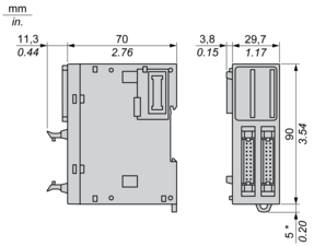
(*) 8.5 mm/0.33 in. when the clamp is pulled out.
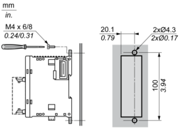
Spacing Requirements

Mounting on a Rail

Incorrect Mounting

Mounting on a Panel Surface

(1) Install a mounting strip
Mounting Hole Layout
Digital Transistor Output Module (32-channel, Sink)
Wiring Diagram
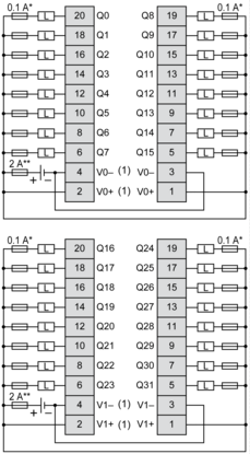
(*) Type T Fuse
(**) Type F Fuse
(1) The V0+ terminals are connected internally.
The V0- terminals are connected internally.
The V1+ terminals are connected internally.
The V1- terminals are connected internally.
The V0+ and V1+ terminals are not connected internally.
The V0- and V1- terminals are not connected internally.
Need more information? Check our technical FAQs!
Easily find answers to the most frequently asked questions.