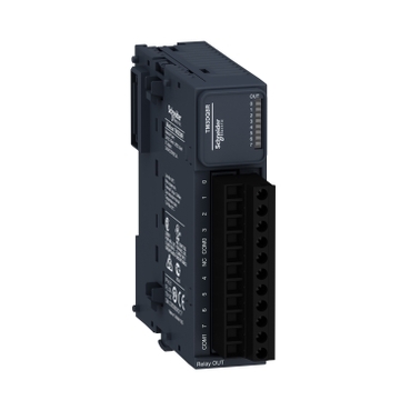
Our Brands

Impact-Company-Logo-English Black-01-177x54

Welcome to the Schneider Electric Website

Welcome to our website.
0
discrete output module, Modicon TM3, 8 relay outputs, screw, 24V DC

TM3DQ8R

Expansion I/O modules for Modicon M221, M241, M251 and M262 controllers
Modularity and easness of installation
Large choice of I/O system to enhance the capabilities of Modicon M2xx plc
Intuitive machine programming with EcoStruxure Machine Expert
Modicon TM3 system allows to Modicon M2xx plc flexible and customizable I/O extension
Environmental Data
Total lifecycle Carbon footprint
52
Use Better
Packaging made with recycled cardboard
information_stroke
Recycled cardboard content is minimum 70% (50% in US). Some orders may include non-recycled cardboard until stock runs out.
Yes
Use Again
Take-back
information_stroke
Whether the product has been included in a global take-back program. Some products are eligible in some geographies, please verify if it's available in your country.
No
arrow2_down
Description
arrow2_down
This product is part of the Modicon TM3 range, an offer of expansion I/O modules for Modicon M221, M241, M251 and M262. The discrete output module provides 8 relay outputs with sink or source (positive/negative) logic. It is an output module with an output voltage of 240V AC, 30V DC and a current consumption of 40mA at 24V DC via bus connector. This product is capable of controlling variable speed drives or any device equipped with a current or voltage input. There is an insulation between output and supply at 1500V AC, output and internal logic at 500V AC. It is furnished with removable screw terminal for electrical connection with 5.08mm pitch adjustment for outputs. It offers mechanical durability of 20 million cycles. It is an IP20 rated product. Its dimensions are 27.4mm (Width) x 84.6mm (Depth) x 90mm (Height). It weighs 0.13kg. This product is certified by CE, CULus and C-Tick. It meets EN/IEC 61131-2 and EN/IEC 61010-2-201 standards. This module is compatible with Modicon M262, Modicon M241, Modicon M251 and Modicon M221 logic controller. It supports top hat type TH35-15, top hat type TH35-7.5 rail conforming to IEC 60715 and plate or panel with fixing kit mount. Modicon TM3 expansion modules have been designed with a simple interlocking assembly mechanism. A bus expansion connector is used to distribute data and the power supply when assembling the Modicon TM3 modules with logic controllers. Boost the performance of your controller with the Modicon TM3 I/O system specially designed for the Modicon M221, M241 and M251 logic controllers.
Specifications
arrow2_down
Main
Range of productModicon TM3
Product or component typeDiscrete output module
Range compatibilityModicon M241
Modicon M251
Modicon M221
Modicon M262
Discrete output logicPositive or negative
Complementary
Mechanical durability20000000 cycles
Maximum cable distance between devicesUnshielded cable: <30 m for relay output
Local signalling1 LED per channel (green) for output status
Mounting supportTop hat type TH35-15 rail conforming to IEC 60715
Top hat type TH35-7.5 rail conforming to IEC 60715
plate or panel with fixing kit
Height90 mm
Width27.4 mm
Depth84.6 mm
Net weight0.11 kg
Environment
MarkingCE
Pollution degree2
Packing Units
Unit Type of Package 1PCE
Number of Units in Package 11
Package 1 Height7.519 cm
Package 1 Width10.487 cm
Package 1 Length12.849 cm
Package 1 Weight240.0 g
Unit Type of Package 2CAR
Number of Units in Package 242
Package 2 Height29.4 cm
Package 2 Width39.7 cm
Package 2 Length56.0 cm
Package 2 Weight10.95 kg
Unit Type of Package 3P12
Number of Units in Package 3504
Package 3 Height105 cm
Package 3 Width120 cm
Package 3 Length80 cm
Package 3 Weight130 kg
arrow2_down
Schneider Electric aims to achieve Net Zero status by 2050 through supply chain partnerships, lower impact materials, and circularity via our ongoing “Use Better, Use Longer, Use Again” campaign to extend product lifetimes and recyclability.
Environmental footprint
Use Better
Materials and Substances
Use Again
Repack and remanufacture
Dimensions Drawings
arrow2_down
Dimensions


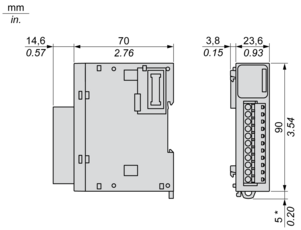
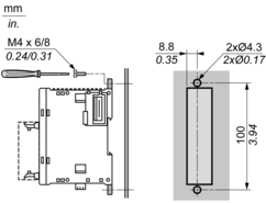
(*) 8.5 mm/0.33 in. when the clamp is pulled out.


Mounting and Clearance
arrow2_down
Spacing Requirements


Mounting on a Rail


Incorrect Mounting


Mounting on a Panel Surface


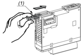
(1) Install a mounting strip
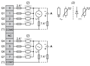
Mounting Hole Layout


Connections and Schema
arrow2_down
Digital Relay Output Module (8-channel)
Wiring Diagram (Positive Logic)


(*) Type T Fuse

(1) The COM0 and COM1 terminals are not connected internally.

(2) To improve the life time of the contacts, and to protect from potential inductive load damage, it is recommended to connect a free wheeling diode in parallel to each inductive DC load or an RC snubber in parallel of each inductive AC load.

(A) Source wiring (positive logic)
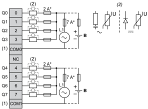
Wiring Diagram (Negative Logic)


(*) Type T fuse

(1) The COM0 and COM1 terminals are not connected internally.

(2) To improve the life time of the contacts, and to protect from potential inductive load damage, it is recommended to connect a free wheeling diode in parallel to each inductive DC load or an RC snubber in parallel of each inductive AC load.

(B) Sink wiring (negative logic)


Documents
arrow2_down
Software and Firmware
arrow2_down

Need more information? Check our technical FAQs!

Easily find answers to the most frequently asked questions.

  • Products Documentation
  • Software Downloads
  • Product Substitution and Replacement
  • Help and Contact Center
  • Find our Offices
  • Where to buy
  • Schneider Electric Community
  • Careers
  • Company Profile
  • Report a misconduct
  • Accessibility
  • Investors
  • EcoStruxure
  • Job Search
  • Blog
  • Privacy Policy
  • Cookie Notice
  • Terms of use
  • Change your cookie settings