
Roll over image to zoom in


XPSUAB31CP
More than 40 different diagnostic messages, without additional fieldbus interface
Reduced down time of the machine due to messages
Status information about upcoming test intervals and amount of remaining cycles before reaching end of life time
ECODESIGN: Optimized Energy Efficiency: Reduction of 24 per cent of CO2 on the whole product life cycle
Reduce risk to an acceptable level
Environmental Data
Total lifecycle Carbon footprint
70
Use Better
Packaging made with recycled cardboard
No
Use Again
Take-back
No
SRVEW1YMSL00
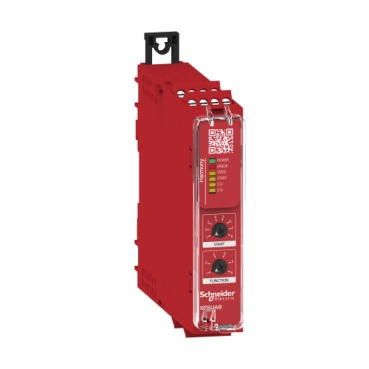
This safety relay is designed for monitoring Emergency stop, Antivalent contacts, Guard switch, Magnetic switch, Proximity safety switch, PNP sensor, RFID safety switch, Safety light curtain or Two-hand control stations. The safety relay is powered with 48-240V AC/DC, and equipped with a screw removable terminal block. This universal safety module embeds pre-defined safety functions, or selectable safety functions via rotary selectors. This safety relay embeds 1 safety input, 2 ON/OFF configurable pulsed outputs, 1 single changeover safety output , and 1 solid state diagnostic output with complete status information. The maximum safety level achieved by this safety relay is PLc conforming to ISO 13849-1, SILCL 1 conforming to IEC 62061 and SIL 1 conforming to IEC 61508. This safety relay weighs 0,200kg. Its dimensions are 22,5mm (Width) x 120mm (Depth) x 100mm (Height). This safety relay weighs 0,200kg. Its dimensions are 22,5mm (Width) x 120mm (Depth) x 100mm (Height). This safety relays is suitable for applications such as Food and Beverage, Hoisting, Material Handling, Material Working, Packaging. This safe relay conforms to IEC60947-5-1, IEC61508-1/2/3, ISO13849-1, IEC62061 functional safety standards, is certified by cULus, TÜV, EAC, CCC and KC marking. Harmony safety relays are compatible with Modicon logic controllers. This relay is mounted on a 35mm symmetrical DIN rail. Harmony XPS Basic and Universal safety relays are the first choice for managing single safety functions easily, typically in machines of simple to medium complexity. Harmony XPS Universal is the first choice for a broad range of simple to mid-complex machines.
| Range of product | Harmony Safety Automation |
|---|---|
| Product or component type | Safety module |
| Safety module name | XPSUAB |
| Safety module application | For electrical monitoring of two-hand control stations For application with safety switchover contact For emergency stop, guard and light curtain monitoring Monitoring antivalent contacts |
| Function of module | Emergency stop monitoring 1-channel wiring Guard monitoring 1-channel wiring Monitoring 1 PNP sensor Monitoring two-hand control station type IIIA Magnetic switch monitoring Light curtain monitoring RFID switch Monitoring of electro-sensitive protection equipment (ESPE) Proximity sensor monitoring |
| Safety level | Can reach PL = c conforming to ISO 13849-1 Can reach SILCL 1 conforming to IEC 62061 Can reach SIL 1 conforming to IEC 61508 |
| Safety reliability data | MTTFd >= 30 years conforming to ISO 13849-1 Dcavg < 60 % conforming to ISO 13849-1 PFHd = 1177E-09 1/h conforming to ISO 13849-1 HFT = 0 conforming to IEC 62061 PFHd = 1177E-09 1/h conforming to IEC 62061 SFF > 60% conforming to IEC 62061 HFT=0 conforming to IEC 61508-1 PFHd = 1177E-09 1/h conforming to IEC 61508-1 SFF > 60% conforming to IEC 61508-1 Type = B conforming to IEC 61508-1 |
| Electrical circuit type | NC pair PNP pair Antivalent pair OSSD pair |
| Connections - terminals | Removable screw terminal block, 0.2...2.5 mm² solid or flexible Removable screw terminal block, 0.25...2.5 mm² flexible with ferrule single conductor Removable screw terminal block, 0.2...1.5 mm² solid or flexible twin conductor Removable screw terminal block, 2 x 0.25...1 mm² flexible with ferrule without cable end, with bezel Removable screw terminal block, 2 x 0.5...1.5 mm² flexible with ferrule with cable end, with bezel |
| [Us] rated supply voltage | 48...240 V AC/DC - 10...10 % |
| Synchronisation time between inputs | 0.5 s 2.2 s |
|---|---|
| Type of start | Automatic/manual/monitored |
| Power consumption in W | 2.0 W 48 V DC |
| Power consumption in VA | 6.5 VA 240 V AC 50/60 Hz |
| Input protection type | Internal, electronic |
| safety outputs | 1 C/O |
| safety inputs | 1 safety input 24 V DC 5 mA |
| maximum wire resistance | 500 Ohm |
| Input compatibility | Normally closed circuit conforming to ISO 14119 XC limit switch conforming to ISO 14119 Mechanical contact conforming to ISO 14119 Normally closed circuit conforming to ISO 13850 Antivalent pair conforming to ISO 14119 OSSD pair conforming to IEC 61496-1-2 Two-hand control conforming to EN 574/ISO 13851-III A 3-wire proximity sensors PNP |
| [Ie] rated operational current | 5 A AC-1 for normally open relay contact 3 A AC-15 for normally open relay contact 5 A DC-1 for normally open relay contact 3 A DC-13 for normally open relay contact 3 A AC-1 for normally closed relay contact 1 A AC-15 for normally closed relay contact 2 A DC-1 for normally closed relay contact 1 A DC-13 for normally closed relay contact |
| Control Outputs | 2 on/off configurable pulsed output |
| Input/output type | Semiconductor pulsed diagnostic output 24 V DC, 20 mA Z1, not safety-related |
| [Ith] conventional free air thermal current | 3 A |
| Associated fuse rating | 6 A gG for relay output conforming to IEC 60947-1 |
| Minimum output current | 10 mA for relay output |
| Minimum output voltage | 15 V for relay output |
| Maximum response time on input open | 20 ms |
| [Ui] rated insulation voltage | 250 V (pollution degree 2) conforming to IEC 60947-1 |
| [Uimp] rated impulse withstand voltage | 4 kV overvoltage category II conforming to IEC 60947-1 |
| Local signalling | LED (green) for power ON LED (red) for error LED (yellow) for start LED (yellow) for safety status LED (yellow) for safety input S12 LED (yellow) for safety input S13 |
| Mounting support | 35 mm symmetrical DIN rail |
| Depth | 120 mm |
| Ambient air temperature for operation | -25…55 °C |
| Height | 100 mm |
| Width | 22.5 mm |
| Net weight | 0.200 kg |
| Standards | IEC 60947-5-1 IEC 61508-1 functional safety standard IEC 61508-2 functional safety standard IEC 61508-3 functional safety standard IEC 61508-4 functional safety standard IEC 61508-5 functional safety standard IEC 61508-6 functional safety standard IEC 61508-7 functional safety standard ISO 13849-1 functional safety standard IEC 62061 functional safety standard |
|---|---|
| Product certifications | TÜV cULus |
| IP degree of protection | IP20 (terminals) conforming to IEC 60529 IP40 (housing) conforming to IEC 60529 IP54 (mounting area) conforming to IEC 60529 |
| Relative humidity | 5…95 % non-condensing |
| Unit Type of Package 1 | PCE |
|---|---|
| Number of Units in Package 1 | 1 |
| Package 1 Height | 6.5 cm |
| Package 1 Width | 13.5 cm |
| Package 1 Length | 15.5 cm |
| Package 1 Weight | 262.0 g |
| Unit Type of Package 2 | S03 |
| Number of Units in Package 2 | 16 |
| Package 2 Height | 30 cm |
| Package 2 Width | 30 cm |
| Package 2 Length | 40 cm |
| Package 2 Weight | 4.939 kg |
Schneider Electric aims to achieve Net Zero status by 2050 through supply chain partnerships, lower impact materials, and circularity via our ongoing “Use Better, Use Longer, Use Again” campaign to extend product lifetimes and recyclability.
Total lifecycle Carbon footprint
70
Environmental Disclosure
Use Better
Packaging made with recycled cardboard
No
Packaging without single use plastic
No
Pro-active compliance (Product out of EU RoHS legal scope)
SCIP Number
152cf799-1df7-4892-81b4-4c890187f1d1
REACh Regulation
PVC free
Yes
Use Again
End of life manual availability
Take-back
No
WEEE Label
The product must be disposed on European Union markets following specific waste collection and never end up in rubbish bins
Dimensions
Front and Side Views

(A) : Product drawing
(B) : Screw clamp terminal
(C) : Side view
(1) : Removable terminal blocks, top
(2) : Removable terminal blocks, bottom
(3) : LED indicators
(4) : Start function selector
(5) : Function selector
(6) : Sealable transparent cover

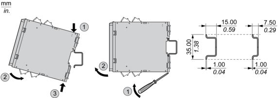
Mounting to DIN rail
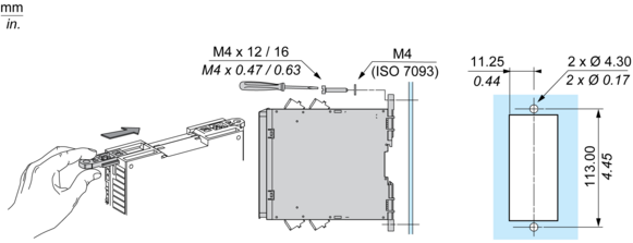
Screw-mounting
Wiring Drawing

(1) : A1-A2 (Power supply)
(2) : S11-S12-S13 (Single-channel safety input)
(3) : Y1-Y2 (Start)
11-12-14 : Output
B2 : Common ground terminal
Z1 : Pulsed output for diagnostics, not safety-related
Need more information? Check our technical FAQs!
Easily find answers to the most frequently asked questions.