


ZB4BS844
Bezel material:
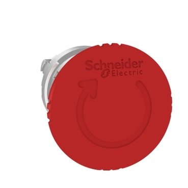
Operator profile:
Reset:


| Range of product | Harmony XB4 |
|---|---|
| Product or component type | Head for emergency switching off push-button |
| Device short name | ZB4 |
| Bezel material | Chromium plated metal |
| Mounting diameter | 22.5 mm |
| Sale per indivisible quantity | 1 |
| Shape of signaling unit head | Round |
| Type of operator | trigger action and mechanical latching |
| Reset | Turn to release |
| Operator profile | Red mushroom Ø 40 mm, unmarked |
| Head type | Standard |
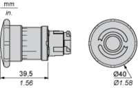
| CAD overall width | 40 mm |
|---|---|
| CAD overall height | 40 mm |
| CAD overall depth | 57 mm |
| Net weight | 0.073 kg |
| Mechanical durability | 300000 cycles |
| Electrical composition code | C7 for <4 contacts using single blocks in front mounting C8 for <4 contacts using single and double blocks in front mounting C11 for <3 contacts using single blocks in front mounting C15 for <1 contacts using single blocks in front mounting C10 for <4 contacts using single and double blocks in front mounting |
| Device presentation | Basic element |
| Protective treatment | TH |
|---|---|
| Ambient air temperature for storage | -40…70 °C |
| Ambient air temperature for operation | -40…70 °C |
| Electrical shock protection class | Class I conforming to IEC 61140 |
| IP degree of protection | IP66 conforming to IEC 60529 IP69 IP69K |
| NEMA degree of protection | NEMA 13 NEMA 4X NEMA 4 NEMA 12 |
| IK degree of protection | IK06 conforming to IEC 50102 |
| Standards | UL 508 IEC 60947-5-5 CSA C22.2 No 14 IEC 60947-5-4 JIS C8201-5-1 IEC 60947-1 IEC 60947-5-1 IEC 60204-1 IEC 60364-5-53 GB 14048.5 ISO 13850 JIS C8201-1 |
| Product certifications | DNV UL listed LROS (Lloyds register of shipping) BV CSA |
| Vibration resistance | 5 gn (f= 2…500 Hz) conforming to IEC 60068-2-6 |
| Shock resistance | 30 gn (duration = 18 ms) for half sine wave acceleration conforming to IEC 60068-2-27 50 gn (duration = 11 ms) for half sine wave acceleration conforming to IEC 60068-2-27 |
| Unit Type of Package 1 | PCE |
|---|---|
| Number of Units in Package 1 | 1 |
| Package 1 Height | 4.400 cm |
| Package 1 Width | 5.400 cm |
| Package 1 Length | 9.200 cm |
| Package 1 Weight | 75.000 g |
| Unit Type of Package 2 | S03 |
| Number of Units in Package 2 | 100 |
| Package 2 Height | 30.000 cm |
| Package 2 Width | 30.000 cm |
| Package 2 Length | 40.000 cm |
| Package 2 Weight | 7.980 kg |
| Unit Type of Package 3 | P06 |
| Number of Units in Package 3 | 800 |
| Package 3 Height | 75.000 cm |
| Package 3 Width | 60.000 cm |
| Package 3 Length | 80.000 cm |
| Package 3 Weight | 75.004 kg |
| Warranty | 18 months |
|---|
Connection by Screw Clamp Terminals or Plug-in Connectors or on Printed Circuit Board | Connection by Faston Connectors |
|
|
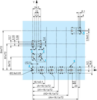
(1) Diameter on finished panel or support (2) 40 mm min. / 1.57 in. min. (3) 30 mm min. / 1.18 in. min. (4) Ø 22.5 mm / 0.89 in. recommended (Ø 22.3 mm 0+0.4 / 0.88 in. 0+0.016) (5) 45 mm min. / 1.78 in. min. (6) 32 mm min. / 1.26 in. min. | |


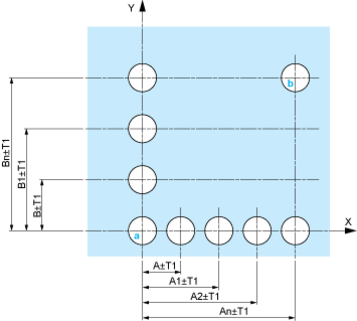
A: 30 mm min. / 1.18 in. min.
B: 40 mm min. / 1.57 in. min.
Dimensions in mm
A: 30 mm min.
B: 40 mm min.
Dimensions in in.

A: 1.18 in. min.
B: 1.57 in. min.
The cumulative tolerance must not exceed 0.3 mm / 0.012 in: T1 + T2 = 0.3 mm max.
Minimum thickness of circuit board: 1.6 mm / 0.06 in.
Cut-out diameter: 22.4 mm ± 0.1 / 0.88 in. ± 0.004
Orientation of body/fixing collar ZB4 BZ009: ± 2°30’ (excluding cut-outs marked a and b).
Tightening torque of screws ZBZ 006: 0.6 N.m (5.3 lbf.in) max.
Allow for one ZB4 BZ079 fixing collar/pillar and its fixing screws:
every 90 mm / 3.54 in. horizontally (X), and 120 mm / 4.72 in. vertically (Y).
with each selector switch head (ZB4 BD•, ZB4 BJ•, ZB4 BG•).
The fixing centers marked a and b are diagonally opposed and must align with those marked 4 and 5.

(1) Panel
(2) Printed circuit board
1 2 elongated holes for ZBZ 006 screw access
2 1 hole Ø 2.4 mm ± 0.05 / 0.09 in. ± 0.002 for centring adapter ZBZ 01•
3 8 × Ø 1.2 mm / 0.05 in. holes
4 1 hole Ø 2.9 mm ± 0.05 / 0.11 in. ± 0.002, for aligning the printed circuit board (with cut-out marked a)
5 1 elongated hole for aligning the printed circuit board (with cut-out marked b)
6 4 holes Ø 2.4 mm / 0.09 in. for clipping in adapter ZBZ 01•
Dimensions An + 18.1 relate to the Ø 2.4 mm ± 0.05 / 0.09 in. ± 0.002 holes for centring adapter ZBZ 01•.


1 N/O

1 N/C

1 N/O + N/C or 1 N/O + N/O or 1 N/C + N/C

Single contact

Double contact

Light block

Possible location

Items usually bought together

Need more information? Check our technical FAQs!
Easily find answers to the most frequently asked questions.