
Roll over image to zoom in


+ 6
4 videos
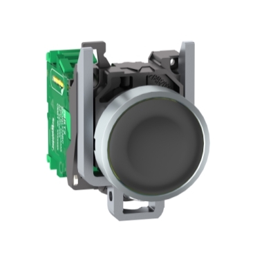
ZB4RTA2
Cap/operator or lens colour:
Marking:
Lower installation costs and time
No setup is needed due to the ready-to-use Plug-and-Play package
Freedom of mobility around the machine or process
Requires no battery maintenance and helps to ensure permanent availability
High resistance to contamination from dust (no cable entry)
Environmental Data
Total lifecycle Carbon footprint
32
Use Better
Packaging made with recycled cardboard
Yes
Use Longer
Product repair index
A
Use Again
Take-back
No


This device is a flush-mounted, wireless, and batteryless metal pushbutton (diameter 22mm). It is equipped with a black cap. The reference ZB4RTA2 includes a transmitter equipped with a fixing collar and a spring return pushbutton head with an attached cap. The cap is factory-assembled and cannot be removed. The transmitter and the receiver communicate via 2.4GHz radio transmission (free worldwide band) Zigbee Green Power. The maximum sensing distance between the transmitter and the receiver in a free field is up to 100m. It is impact-resistant, dust-resistant, water-resistant, and vibration-resistant thanks to its IK03, IP66, IP67, IP69 and IP69K rating. This pushbutton head is ideal for situations where quick actions are required for a process or machine to function correctly. The wireless and battery-less interfaces are used for building utilities (automatic doors, lighting, etc.) and industrial applications (conveying systems, automotive, MMM, logistics, food and beverage). It complies with various radio agreements such as ANATEL, ARIB T66, FCC, ICASA, and RSS, as well as the standards of CSA C22.2 No 14, EN/IEC 60947-1, EN/IEC 60947-5-1, and UL 508. The Harmony XB5R range of wireless and battery-less interfaces suits various building utilities and industrial applications.
| Range of product | Harmony XB5 |
|---|---|
| Product or component type | Wireless and batteryless transmitter |
| Device short name | XB5R |
| Bezel material | Chromium plated metal |
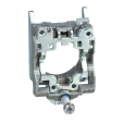
| Fixing collar material | Zamak |
| Mounting diameter | 22 mm |
| Transmission frequency | 2405 MHz |
| emission class | 5M00G7W |
| Antenna type | Omnidirectional |
| Shape of signaling unit head | Round |
|---|---|
| Type of operator | spring return push-button with transmitter |
| Operator profile | Black flush |
| Max power consumption in W | 1 mW |
| Number of channels | 16 |
| Modulation Technique | O-QPSK |
| Bandwidth | 5 MHz |
| Antenna gain | 0 dBi |
| Embedding depth | 42 mm |
| CAD overall height | 41.5 mm |
| CAD overall width | 30 mm |
| CAD overall depth | 43 mm |
| Net weight | 0.045 kg |
| Operating travel | 4.3 mm (total travel) |
| Operating force | 10 N C/O changing electrical state |
| Mechanical robustness | Free fall resistance 1000 mm conforming to IEC 60068-2-32 |
| Standards | CSA C22.2 No 14 IEC 60947-1 IEC 60947-5-1 UL 508 |
| Radio agreement | ANATEL ARIB T66 FCC ICASA RSS |
| Communication port protocol | Zigbee green power at 2.4 GHz conforming to IEEE 802.15.4 |
| Maximum sensing distance | 100 m in free field 25 m transmitter in a plastic box type XAL D and receiver in a metal enclosure 300 m transmitter in box type XAL D, receiver in metal enclosure and use relay-antenna |
| Acquisition time | 2 ms |
| Response time | < 2 ms |
| Emission power | 3 mW |
| Fixing mode | Fixing screw beneath head: 0.8…1.2 N.m |
| Electrical composition code | PW1 |
| Protective treatment | TH |
|---|---|
| Ambient air temperature for storage | -40…70 °C |
| Ambient air temperature for operation | -40…70 °C |
| Relative humidity | 95 % at -40…70 °C without condensation |
| IP degree of protection | IP66 (front face) conforming to IEC 60529 IP67 (front face) conforming to IEC 60529 IP69 (front face) conforming to IEC 60529 IP69K (front face) conforming to IEC 60529 |
| IK degree of protection | IK03 conforming to IEC 50102 |
| Mechanical durability | 1000000 cycles |
| Shock resistance | 25 gn (duration = 6 ms) for 6000 shocks conforming to IEC 60068-2-27 30 gn (duration = 18 ms) for half sine wave acceleration conforming to IEC 60068-2-27 50 gn (duration = 11 ms) for half sine wave acceleration conforming to IEC 60068-2-27 |
| Vibration resistance | 5 gn (f= 11…500 Hz) conforming to IEC 60068-2-6 +/- 10 mm (f= 2…11 Hz) conforming to IEC 60068-2-6 |
| Electromagnetic compatibility | Electrostatic discharge immunity test - test level: 8 kV (in free air (in insulating parts)) conforming to IEC 61000-4-2 Electrostatic discharge immunity test - test level: 4 kV (on contact (on metal parts)) conforming to IEC 61000-4-2 Susceptibility to electromagnetic fields - test level: 20 V/m (80...3000 MHz) conforming to IEC 61000-4-3 Susceptibility to electromagnetic fields - test level: 6 V/m (3000...6000 MHz, distance = 20 m) conforming to IEC 61000-4-3 |
| Product certifications | GOST C-Tick UL BT 2006/95/EC CSA |
| Directives | 1999/5/EC - R&TTE directive 2004/108/EC - electromagnetic compatibility |
| Unit Type of Package 1 | PCE |
|---|---|
| Number of Units in Package 1 | 1 |
| Package 1 Height | 3.0 cm |
| Package 1 Width | 5.6 cm |
| Package 1 Length | 8.4 cm |
| Package 1 Weight | 94.0 g |
| Unit Type of Package 2 | S01 |
| Number of Units in Package 2 | 25 |
| Package 2 Height | 15.0 cm |
| Package 2 Width | 15.0 cm |
| Package 2 Length | 40.0 cm |
| Package 2 Weight | 2.534 kg |
| Warranty | 18 months |
|---|
Schneider Electric aims to achieve Net Zero status by 2050 through supply chain partnerships, lower impact materials, and circularity via our ongoing “Use Better, Use Longer, Use Again” campaign to extend product lifetimes and recyclability.
Total lifecycle Carbon footprint
32
Use Better
Packaging made with recycled cardboard
Yes
Packaging without single use plastic
Yes
Pro-active compliance (Product out of EU RoHS legal scope)
SCIP Number
E1d47e89-a4e1-4f33-a0c0-2fe5c9179aa4
REACh Regulation
Use Longer
Product repair index
A
Use Again
End of life manual availability
Take-back
No
WEEE Label
The product must be disposed on European Union markets following specific waste collection and never end up in rubbish bins
Wireless and Batteryless Pushbutton - Transmitter
With Metal Pushbutton without Cap

e: panel thickness 1 to 6 mm / 0.039 to 0.24 in.
Transmitter Mounting

Transmitter Clearance in Free Field Unobstructed
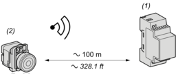
(1): Receiver
(2): Transmitter
Transmitter Clearance in a Metal Enclosure

(1): Metal enclosure
(2): Transmitter
The range is reduced if the transmitter is placed in a metal enclosure (reduction factor:approx 10%)
Glass window | 10...20 % |
Plaster wall | 30...45 % |
Brick wall | 60 % |
Concrete wall | 70...80 % |
Metal structure | 50...100 % |
Need more information? Check our technical FAQs!
Easily find answers to the most frequently asked questions.