
Roll over image to zoom in


+ 5
3 videos
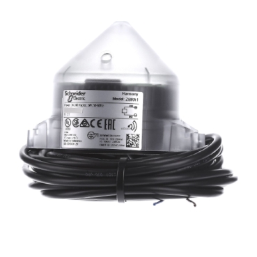
ZBRA1
Quick and easy assembly and disassembly
Robustness to withstand harsh environments
With various types of connection: screw clamp, connector, Faston connector, spring terminal, or printed circuit board
A wide choice of contact blocks for general purposes or specific applications (low current, standard)
Excellent mechanical connection with operator head
Environmental Data
Total lifecycle Carbon footprint
2
Use Better
Packaging made with recycled cardboard
Yes
Use Again
Take-back
No


This relay antenna is part of the range Harmony XB5R plastic and XB4R metal wireless and batteryless pushbuttons. Installed between transmitter and receiver it is used to increase the range and/or get round obstacles. It is impact resistant, dust resistant, water resistant and vibration resistant thanks to its IP65. It makes it ideal for operation in harsh environments.
| Range of product | Harmony XB5R |
|---|---|
| Product or component type | Wireless and batteryless range |
| Device short name | ZBRA |
| Product destination | Wireless Schneider Electric ecosystem devices |
| Control station application | Transceiver (emission and reception) |
| Colour of base of enclosure | Black (RAL 9011) |
| Colour of cover | Transparent |
| Material | Polycarbonate |
| frequency | 2405 MHz for transmitter 2405 MHz for receiver |
| emission class | 5M00G7W |
| Antenna type | Omnidirectional |
| Communication port protocol | Zigbee green power at 2.4 GHz conforming to IEEE 802.15.4 |
|---|---|
| Antenna gain | 0 dBi |
| Maximum sensing distance | 300 m transmitter in box type XAL D, receiver in metal enclosure and use relay-antenna |
| Emission power | 3 mW |
| [Us] rated supply voltage | 24...240 V AC/DC 50/60 Hz - 10...10 % |
| Maximum power consumption in W | 4 W AC/DC |
| Operating position | Vertical |
| Status LED | 1 LED green for power ON 1 LED green for emission signal |
| Overvoltage category | III conforming to IEC 60664-1 |
| Rated short-duration power frequency withstand voltage | 4 kV 50 Hz conforming to IEC 60947-5-1 |
| [Uimp] rated impulse withstand voltage | 4 kV |
| Electrical connection | 2 conductors cable 0.34 mm² - flexible - 5 m conforming to IEC 60947-1 |
| Tightening torque | 0.6 N.m conforming to IEC 60947-1 |
| Housing material | Self-extinguishing plastic |
| Short-circuit protection | 0.4 A fuse type fast blow |
| Max power consumption in W | 1 mW |
| Number of channels | 1 |
| Modulation Technique | O-QPSK |
| Bandwidth | 5 MHz |
| Net weight | 0.2 kg |
| Ambient air temperature for storage | -40…70 °C |
|---|---|
| Relative humidity | 90 % at -20…55 °C, without condensation conforming to ETSI EN 300 440-1 |
| Electrical shock protection class | Class II conforming to IEC 61140 |
| IP degree of protection | IP65 conforming to IEC 60529 55 °C 0.1 m |
| Pollution degree | 3 conforming to IEC 60664-1 |
| IK degree of protection | IK03 conforming to IEC 62262 |
| Radio agreement | RSS SRRC ANATEL, type III conforming to ETSI EN 301 489-3 ARIB T66, class 2 conforming to ETSI EN 301 489-3 FCC, category 2 conforming to ETSI EN 300 440-1 ICASA, category 1 conforming to ETSI EN 300 440-1 |
| Product certifications | CCC BT 2006/95/EC UL GOST CSA CE C-Tick |
| Directives | 1999/5/EC - R&TTE directive 2004/108/EC - electromagnetic compatibility |
| Vibration resistance | +/-0.5 mm (f= 10…55 Hz) conforming to IEC 60068-2-6 6 gn (f= 55…150 Hz) conforming to IEC 60068-2-6 |
| Shock resistance | 25 gn (duration = 6 ms) for 6000 shocks conforming to IEC 60068-2-27 15 gn (duration = 11 ms) for half sine wave acceleration conforming to IEC 60068-2-27 |
| Insulation resistance | > 500 MOhm at 500 V DC conforming to NF C 20030 |
| [Ui] rated insulation voltage | 250 V conforming to IEC 60664-1 |
| Electromagnetic compatibility | Immunity for industrial environments conforming to IEC 61000-6-2 Conducted and radiated emissions class B conforming to CISPR 22 Electrostatic discharge immunity test - test level: 8 kV (in free air (in insulating parts)) conforming to IEC 61000-4-2 Electrostatic discharge immunity test - test level: 6 kV (on contact (on metal parts)) conforming to IEC 61000-4-2 Susceptibility to electromagnetic fields - test level: 10 V/m (80...2000 MHz) conforming to IEC 61000-4-3 Susceptibility to electromagnetic fields - test level: 3 V/m (80...2700 MHz, distance = 20 m) conforming to IEC 61000-4-3 Electrical fast transient/burst immunity test - test level: 2 kV conforming to IEC 61000-4-4 1.2/50 µs shock waves immunity test - test level: 1 kV (differential mode) conforming to IEC 61000-4-5 1.2/50 µs shock waves immunity test - test level: 2 kV (common mode) conforming to IEC 61000-4-5 Conducted RF disturbances - test level: 10 V conforming to IEC 61000-4-6 Immunity to microbreaks and voltage drops conforming to IEC 61000-4-11 Radiated emission conforming to ETSI EN 300 440-1 Conducted emission conforming to EN 300-489-1 Conducted emission conforming to ETSI EN 300 489-3 Radiated emission conforming to ETSI EN 300 440-2 |
| Unit Type of Package 1 | PCE |
|---|---|
| Number of Units in Package 1 | 1 |
| Package 1 Height | 8.000 cm |
| Package 1 Width | 8.000 cm |
| Package 1 Length | 18.700 cm |
| Package 1 Weight | 267.000 g |
| Unit Type of Package 2 | S03 |
| Number of Units in Package 2 | 18 |
| Package 2 Height | 30.000 cm |
| Package 2 Width | 30.000 cm |
| Package 2 Length | 40.000 cm |
| Package 2 Weight | 5.293 kg |
| Warranty | 18 months |
|---|
Schneider Electric aims to achieve Net Zero status by 2050 through supply chain partnerships, lower impact materials, and circularity via our ongoing “Use Better, Use Longer, Use Again” campaign to extend product lifetimes and recyclability.
Total lifecycle Carbon footprint
2
Use Better
Packaging made with recycled cardboard
Yes
Packaging without single use plastic
Yes
Pro-active compliance (Product out of EU RoHS legal scope)
SCIP Number
25b7f895-3732-43c8-9910-ef6005058640
REACh Regulation
Use Again
End of life manual availability
Take-back
No
WEEE Label
The product must be disposed on European Union markets following specific waste collection and never end up in rubbish bins
Relay-Antenna
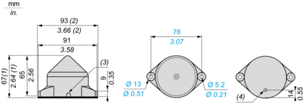
(1) Knock-out for wire routing, maximum capacity 14 mm/0.55 in.
(2) With seal
(3) Radial cable route
(4) Axial cable route
Antenna Mounting
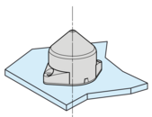
The antenna is installed following his vertical axis
Antenna Clearance in a Metal Enclosure
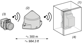
(1): Metal enclosure
(2): Relay Antenna
(3): Transmitter
(4): Receiver
The range is reduced if the transmitter is placed in a metal enclosure (reduction factor:approx 10%).
Glass window | 10...20 % |
Plaster wall | 30...45 % |
Brick wall | 60 % |
Concrete wall | 70...80 % |
Metal structure | 50...100 % |
Relay-Antenna
Wiring Diagram

(1) 400 mA fast-blow fuse
Need more information? Check our technical FAQs!
Easily find answers to the most frequently asked questions.