Issue
At times it is necessary to measure the switching time of an automatic transfer switch (ATS) to validate compatibility with attached downstream equipment.
Product Line
Environment
Resolution
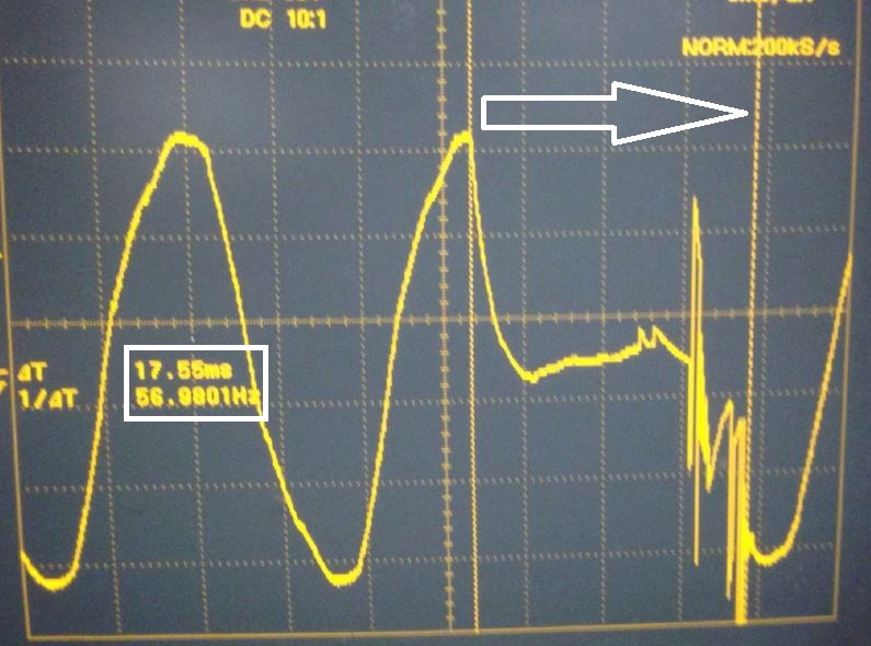
The APC ATS has a maximum switch time (at 60Hz) of 16 milliseconds (ms). In the photo below, the cursors are marking the time when AC signal is removed from the load, to the point when a perfect sine wave is displayed again:

When measured in this way, the transfer time appears to be 17.55 ms; however looking at the wave form the actual switch occurs much sooner than when it was measured. In the picture below, we use the same wave form but set the cursors to the point where energy is again being delivered to the load after switching sources:

The jagged waveform between the actual source switch and the clean sine wave is the result of loading during the switch operation, as well as mechanical relay 'contact bounce'. The properly measured switch time in 13.55 ms.
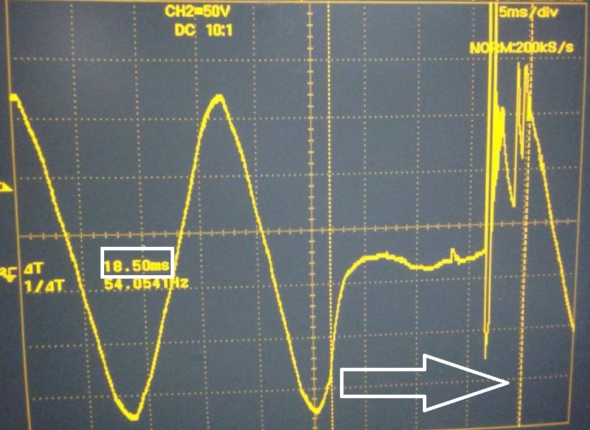
Another incorrect measurement (18.5 ms):

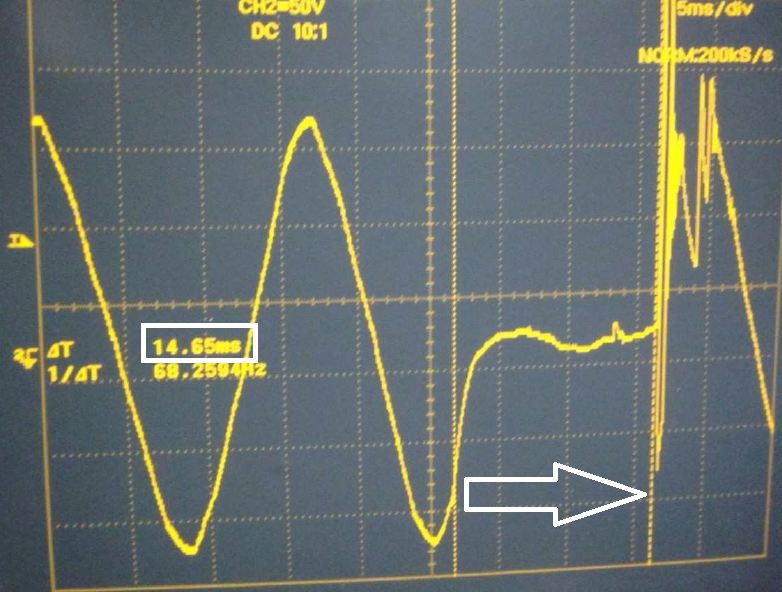
And the correct measurement (14.65 ms):

The transfer of power between sources is complete when the relay closes and energy is again being delivered to the load. Any relay contact bounce and load inrush after that is still transferring power to the load, and will guarantee minimal (<16 ms at 60 Hz or <18 ms at 50 Hz) interruption of power to the load.
At times it is necessary to measure the switching time of an automatic transfer switch (ATS) to validate compatibility with attached downstream equipment.
Product Line
- AP77XX series Automatic Transfer Switches (all generations)
Environment
- All firmware versions (unless otherwise noted)
- All serial numbers
Resolution
The APC ATS has a maximum switch time (at 60Hz) of 16 milliseconds (ms). In the photo below, the cursors are marking the time when AC signal is removed from the load, to the point when a perfect sine wave is displayed again:
When measured in this way, the transfer time appears to be 17.55 ms; however looking at the wave form the actual switch occurs much sooner than when it was measured. In the picture below, we use the same wave form but set the cursors to the point where energy is again being delivered to the load after switching sources:
The jagged waveform between the actual source switch and the clean sine wave is the result of loading during the switch operation, as well as mechanical relay 'contact bounce'. The properly measured switch time in 13.55 ms.
Another incorrect measurement (18.5 ms):
And the correct measurement (14.65 ms):
The transfer of power between sources is complete when the relay closes and energy is again being delivered to the load. Any relay contact bounce and load inrush after that is still transferring power to the load, and will guarantee minimal (<16 ms at 60 Hz or <18 ms at 50 Hz) interruption of power to the load.

