View all
Altivar 71 Plus-LH

ATV71EXC2C20N4H
ATV71EXC2C20N4H
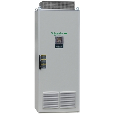
enclosed variable speed drive ATV71 Plus-LH - 200 KW - 400V - IP23- low harmonic
Show more characteristics-
Characteristics
Main range of product Altivar 71 Plus-LHproduct or component type Variable speed drivedevice short name ATV71product destination Synchronous motorsAsynchronous motorsassembly style In floor-standing enclosure compact versionkit composition ATV71HC20N4 standard drive IP00A line chokeControl transformer 230 V ACAn IP65 remote mounting kit for graphic display terminalTerminals/bars for motor connectionA wired ready-assembled Schneider Spacial SF enclosurePower supply 24 V DCClean power filter with integrated EMC filterA switch and fast-acting fusesActive infeed converterComplementary EMC filter Integratednetwork number of phases 3 phases[Us] rated supply voltage 380...415 V +/- 10 %supply voltage limits 342…457 Vsupply frequency 50...60 Hz +/- 5 %network frequency limits 47.5…63 Hzmotor power kW 200 kW, 3 phases at 380...415 Vline current 320 A at 400 V3 phases / 200 kWapparent power 222 kVA for 400 V, 3 phases 200 kWprospective line Isc 100 kA with external fuses100 kA with option circuit breakercontinuous output current 387 A, 2.5 kHz at 400 V 3 phasesmaximum transient current 580 A (duration=60 s) at 400 V 3 phasesspeed drive output frequency 0.1…500 Hznominal switching frequency 2.5 kHzswitching frequency 2...8 kHz adjustable2.5...8 kHz with derating factorspeed range 1…100 in open-loop mode, without speed feedbackspeed accuracy +/- 0.01 % of nominal speed 0.2 Tn to Tn in closed-loop mode with encoder feedback+/- 10 % of nominal slip 0.2 Tn to Tn without speed feedbacktorque accuracy +/- 15 % in open-loop mode, without speed feedback+/- 5 % in closed-loop mode with encoder feedbacktransient overtorque 170 % of nominal motor torque +/- 10 % for 60 s220 % of nominal motor torque +/- 10 % for 2 sbraking torque 100 % continuous120 % for 60 secondsasynchronous motor control profile Voltage/frequency ratio (2 or 5 points)Vector control with/without speed feedbackENA (Energy adaptation) system for unbalanced loadssynchronous motor control profile Vector control with sensor, standardVector control without sensor, standardregulation loop Adjustable PI regulatormotor slip compensation Automatic whatever the loadAdjustableNot available in voltage/frequency ratio (2 or 5 points)Can be suppressedovervoltage category Class 3 conforming to EN 50178local signalling LCD display unitoperation function, status and configuration - mounted in the front door:output voltage <= power supply voltageisolation Between power and control terminalstype of cable IEC cable at 40 °C, copper 70 °C / PVCelectrical connection Terminal - 2.5 mm² / AWG 14 (AI1-/AI1+, AI2, AO1, R1A, R1B, R1C, R2A, R2B, LI1...LI6, PWR) entry from the bottomTerminal M10 - 2 x 300 mm² (L1/R, L2/S, L3/T) entry from the bottomTerminal M12 - 4 x 240 mm² (U/T1, V/T2, W/T3) entry from the bottommotor recommanded cable cross section 2 (3 x 120) mm²short-circuit protection 500 A for fuse 3 gI power supply upstreamsupply External supply: 24 V (19…30 V)DC, <1 A, 30 WInternal supply for reference potentiometer: 10 V (10…11 V)DC, <10 mAInternal supply: 24 V (21…27 V)DC, <100 mAanalogue input number 2analogue input type AI2 software-configurable voltage: 0...10 V DC, 24 V max, impedance: 30 kOhm, sampling time: 1.5…2.5 ms, resolution: 11 bitsAI1-/Al1+ bipolar differential voltage: +/- 10 V DC, 24 V max, sampling time: 1.5…2.5 ms, resolution: 11 bits + signAI2 software-configurable current: 0...20 mA/4...20 mA, impedance: 250 Ohm, sampling time: 1.5…2.5 ms, resolution: 11 bitsanalogue output number 1analogue output type Software-configurable voltage: (AO1) 0...10 V DC - 470 Ohm - sampling time: 1.5…2.5 ms - resolution: 10 bitsSoftware-configurable current: (AO1) 0...20 mA/4...20 mA - 500 Ohm - sampling time: 1.5…2.5 ms - resolution: 10 bitsdiscrete output number 1discrete output type Configurable relay logic: (R1A, R1B, R1C)NO/NC - 6.5...7.5 ms - 100000 cyclesminimum switching current 3 mA at 24 V DC (configurable relay logic)maximum switching current 5 A at 250 V AC on resistive load - cos phi = 1 for configurable relay logic5 A at 30 V DC on resistive load - L/R = 0 ms for configurable relay logic2 A at 250 V AC on inductive load - cos phi = 0.4 for configurable relay logic2 A at 30 V DC on inductive load - L/R = 7 ms for configurable relay logicdiscrete input number 6discrete input type Programmable (LI1...LI4) at 24 V DC <= 30 V level 1 PLC 3.5 kOhm (duration=1.5…2.5 ms)Switch-configurable (LI6) at 24 V DC <= 30 V level 1 PLC 1.5 kOhm (duration=1.5…2.5 ms)Safety input (PWR) at 24 V DC <= 30 V 1.5 kOhmdiscrete input logic Positive logic (source) (LI1...LI6), 0...5 V (state 0), 11...30 V (state 1)Negative logic (sink) (LI1...LI6), 16...30 V (state 0), 0...10 V (state 1)Positive logic (source) (PWR), 0...2 V (state 0), 17...30 V (state 1)acceleration and deceleration ramps S, U or customizedLinear adjustable separately from 0.01 to 9000 sbraking to standstill By regenerative braking with active front endprotection type Against exceeding limit speed: driveAgainst input phase loss: driveLine supply overvoltage: driveLine supply undervoltage: driveOvercurrent between output phases and earth: driveOverheating protection: driveOvervoltages on the DC bus: drivePower removal: driveShort-circuit between motor phases: driveThermal protection: motorMotor phase break: motordielectric strength 3535 V DC between earth and power terminals5092 V DC between control and power terminalsinsulation resistance > 1 mOhm 500 V DC for 1 minute to earthfrequency resolution Analog input: 0.024/50 HzDisplay unit: 0.1 Hzcommunication port protocol CANopenModbusconnector type 1 RJ45 (on front face) for Modbus1 RJ45 (on terminal) for ModbusMale SUB-D 9 on RJ45 for CANopenphysical interface 2-wire RS 485 for Modbustransmission frame RTU for Modbustransmission rate 4800 bps, 9600 bps, 19200 bps, 38.4 Kbps for Modbus on terminal9600 bps, 19200 bps for Modbus on front face20 kbps, 50 kbps, 125 kbps, 250 kbps, 500 kbps, 1 Mbps for CANopendata format 8 bits, 1 stop, even parity for Modbus on front face8 bits, odd even or no configurable parity for Modbus on terminaltype of polarization No impedance for Modbusnumber of addresses 1…127 for CANopen1…247 for Modbusmethod of access Slave CANopenfunction available Safe standstill for power circuitPTC relay for power circuitPt100 relay for power circuitInsulation monitoring for power circuitDesign for IT networks for power circuitExternal 230 V supply terminals for power circuitBuffer voltage 24 V DC power supply for power circuitEnclosure lighting for power circuitKey switch (local/remote) for power circuitMotor heating for power circuitExternal motor fan for power circuitVoltmeter for power circuitDoor handle for main switch for power circuitAmmeter for power circuitEnclosure heating for power circuitMotor choke for power circuitCable entry via the top for power circuitEnclosure plinth for power circuitRelay output C/O for control circuitExternal 24 V DC supply terminals for power circuitControl terminals for control circuitAdaptor for 115 V logic inputs for control circuitIsolated amplifier for control circuitoption card Communication card for CC-LinkCommunication card for DeviceNetCommunication card for Ethernet/IPCommunication card for FipioCommunication card for Interbus-SCommunication card for Modbus PlusCommunication card for Modbus TCPCommunication card for Modbus/Uni-TelwayCommunication card for Profibus DPCommunication card for Profibus DP V1Controller inside programmable cardBasic I/O extension cardExtended I/O extension cardEncoder interface cardsoperating position Vertical +/- 10 degreecolour of enclosure Light grey (RAL 7035)width 1600 mmheight 2157 mmdepth 642 mmnet weight 980 kgEnvironment IP degree of protection IP23standards EN 61800-2EN 61800-5-1EN 60204-1EN 61800-3 environments 2 category C3product certifications GOSTC-TickATEXmarking CEnoise level 70 dBpollution degree 2 conforming to EN/IEC 61800-5-1vibration resistance 0.6 gn (f= 10…200 Hz) conforming to EN/IEC 60068-2-61.5 mm peak to peak (f= 3…10 Hz) conforming to EN/IEC 60068-2-63M3 conforming to EN/IEC 60721-3-3shock resistance 4 gn for 11 ms conforming to EN/IEC 60068-2-273M2 conforming to EN/IEC 60721-3-3environmental characteristic 3K3 without condensation conforming to IEC 60721-3-3relative humidity 0…95 %ambient air temperature for operation 0…40 °C (without)40…50 °C (with current derating of 1.8 % per °C)ambient air temperature for storage -25…70 °Cvolume of cooling air 2400 m3/hoperating altitude <= 1000 m without1000...3000 m with current derating 1 % per 100 mContractual warranty Warranty 18 months -
View more
Documents
Language- English2
CatalogueFormatSizeAdd to My DocumentsCatalog: Altivar 71/71 Plus variable speed drives - English version 2014/04 (web pdf format) (Version 1.0)Size pdfSize 10.7 MBDate 18/06/14CertificateFormatSizeAdd to My Documents -
Technical FAQs
No results found.Unfortunately, related FAQs are unavailable due to temporary technical issues. Please try again later. -
Dimensions Drawings
Dimensions -
Connections and Schema
Wiring DiagramA1DriveA2EnclosureAICActive Infeed ConverterMMotorQ1Main switch built-in as standardQ2Optional circuit breakerF1Main fusesKM1Line contactorEMCEMC filterLFCLine Filter Choke(1)Control(2)Relay control(3)Reference potentiometer(4)Option motor choke -
Performance Curves
Derating CurvesThe derating curves for the drive nominal current (In) are dependent on the temperature and switching frequency. For intermediate temperatures, interpolate between 2 curves.
NOTE: The drive will reduce the switching frequency automatically in the event of excessive temperature rise.
XSwitching frequency (kHz)NOTE: The temperatures shown correspond to the temperature of the air entering the enclosure.