
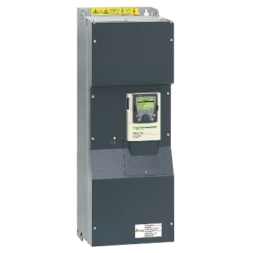

variable speed drive ATV71Q - 110kW / 150HP - 380...480V - IP20
Local distributor code:
398229483
ATV71QC11N4
Discontinued on:22 Sept 2021
Recommended replacement(s)
EAN Code: 3606480388941
Sustainability
Green PremiumTM label is Schneider Electric’s commitment to delivering products with best-in-class environmental performance.
Green Premium promises compliance with the latest regulations, transparency on environmental impacts, as well as circular and low-CO2 products.
Guide to assessing product sustainability is a white paper that clarifies global eco-label standards and how to interpret environmental declarations.
Guide to assessing product sustainability is a white paper that clarifies global eco-label standards and how to interpret environmental declarations.
Well-being performance
Mercury free
RoHS exemption information
EU RoHS Directive
Pro-active compliance (Product out of EU RoHS legal scope)
China RoHS Regulation
WEEE
The product must be disposed on European Union markets following specific waste collection and never end up in rubbish bins
ATV71QC11N4 is replaced by the following product range: