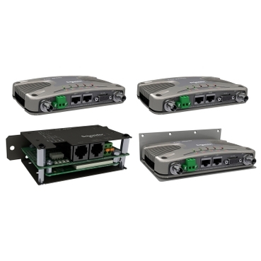
Overview
Both the Trio Q and Trio J radios have a multi-use serial port. Each radio features a 9 pin miniature D-Shell (DE-9) female connector that supports two individual serial port connections.
Typical use case for the J (unlicensed 900Mhz/2.4Ghz) or Q (licensed 150Mhz/450Mhz) radios will be Ethernet communications. Yet for legacy applications, a Modbus Gateway (Modbus TCP to RTU protocol converter), or Modbus Serial Device Server (Modbus RTU in TCP) may be configured on the serial port. A serial port may also be configured as a TUI (Text User Interface) for configuration/diagnostics. The TUI diagnostics is useful on systems suffering from high error rates as it provides a basic high speed interface.
Serial port configuration is accomplished with a web browser and the default IP address of both radios is 192.168.2.15. Details of how to configure each radio’s serial port for your application can be found in the Q or J radio documentation installed with TVew+.
Serial Port A & B (J series Radio)
Data Port A uses pins 2 & 3 with pin 5 as the common ground*
Data Port B uses pins 4 & 6 with pin 5 as the common ground*
| RS-232 Mode | ||
|---|---|---|
| Pin | Name | Input / Output |
| 1 | Not Used | --- |
| 2 | Port A RxD | Output |
| 3 | Port A TxD | Input |
| 4 | Port B TxD (Diags) | Input |
| 5 | GND | --- |
| 6 | Port B RxD (Diags) | Output |
| 7 | Not Used | --- |
| 8 | Not Used | --- |
| 9 | RSSI / General Purpose Pin | Output |
* There is no option for RS-485 connections with the J Series radio.
COM Port 1 & 2 (Q series Radio)
COM 1 uses pins 2,3,7 & 8 with pin 5 as the common ground
COM 2 uses pins 4 & 6 with pin 5 as the common ground
| RS-232 Mode | RS-485 Mode | |||
|---|---|---|---|---|
| Pin | Name | Input / Output | Name | Input / Output |
| 1 | COM 1 DCD | Output | Not Used | --- |
| 2 | COM 1 RxD | Output | B / Z (Inverting) | Input / Output |
| 3 | COM 1 TxD | Input | A / Y (Non-Inverting) | Input / Output |
| 4 | COM 2 TxD | Input | Not Used | --- |
| 5 | GND | --- | Not Used | --- |
| 6 | COM 2 RxD | Output | Not Used | --- |
| 7 | COM 1 RTS | Input | Not Used | --- |
| 8 | COM 1 CTS | Output | Not Used | --- |
| 9 | RSSI | Output | RSSI | Output |
Released for: Schneider Electric Vietnam