Issue
How do I configure the Modbus TCP IO Scanner for M221 and what addresses do we use to read and write from the remote device?
Product Line
EcoStruxure Machine Expert-Basic, SoMachine Basic, Modicon M221
Environment
PLC configuration software for Windows
Resolution
Follow the example steps below:
1) Go to the Configuration Tab in SoMachine Basic (or EcoStruxure Machine Expert-Basic)
2) Expand ETH1
3) Select Modbus TCP IOScanner
4) In the Modbus TCP area to the right,
(A) Tick the "Modbus TCP IOScanner" checkbox to Activate it
(B) Enter the IP Address of your remote Ethernet server - in our example, we are using 192.168.0.100
(C) Click Add - this will create a Device Row representing your device and a set of addresses to read to, write from, or both.
(D) Click on the [...] button under the "Channels" column
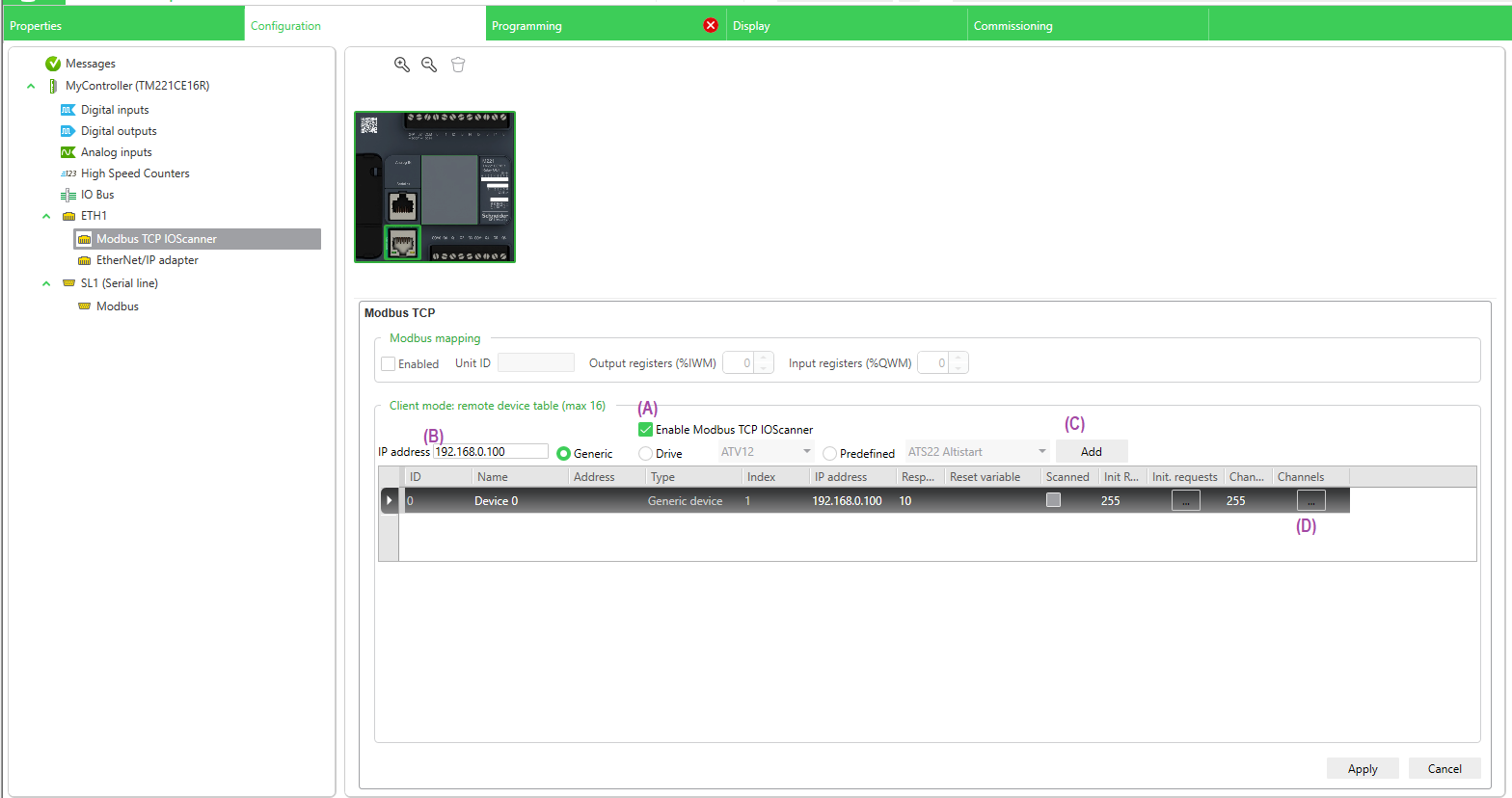
Clicking the [...] button will bring up the Channel Assistant screen:
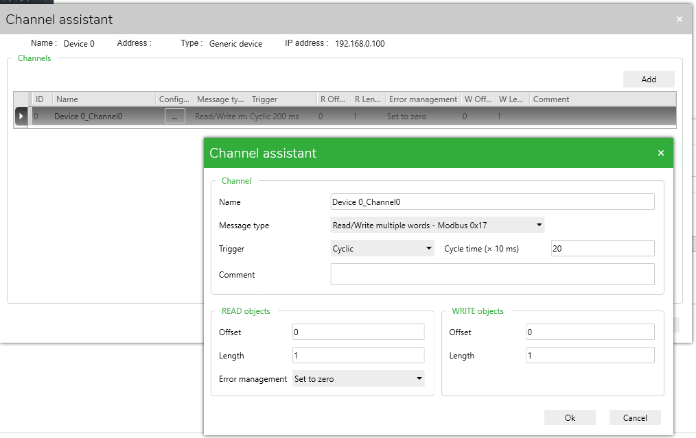
5) In the Message Type dropdown, you can choose various Modbus function codes. Here are the supported Modbus function codes on the M221. We will use Function Code 23 (0x17) Read and Write registers:
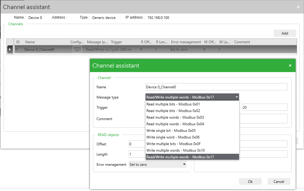
6) In our example, we will keep it as Read/Write multiple words.
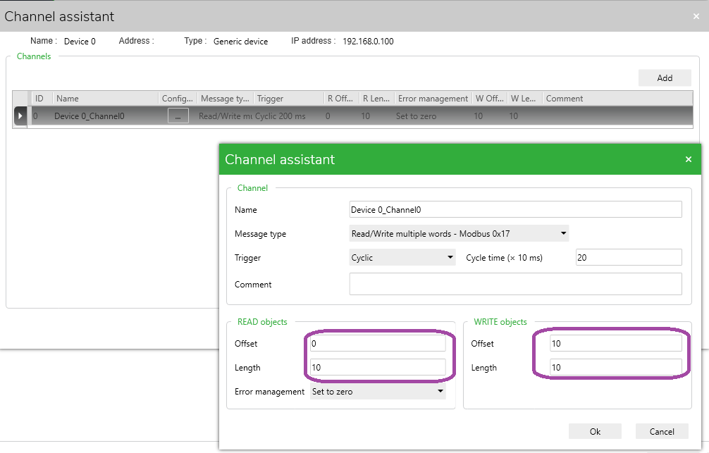
Let’s say we have a Remote I/O Device that has 10 Analog inputs at %MW0 to %MW9 and 10 Analog Outputs at %MW10 to %MW20, we would set up the offset and lengths accordingly:
7) Now, go to the Programming Tab on the top bar.
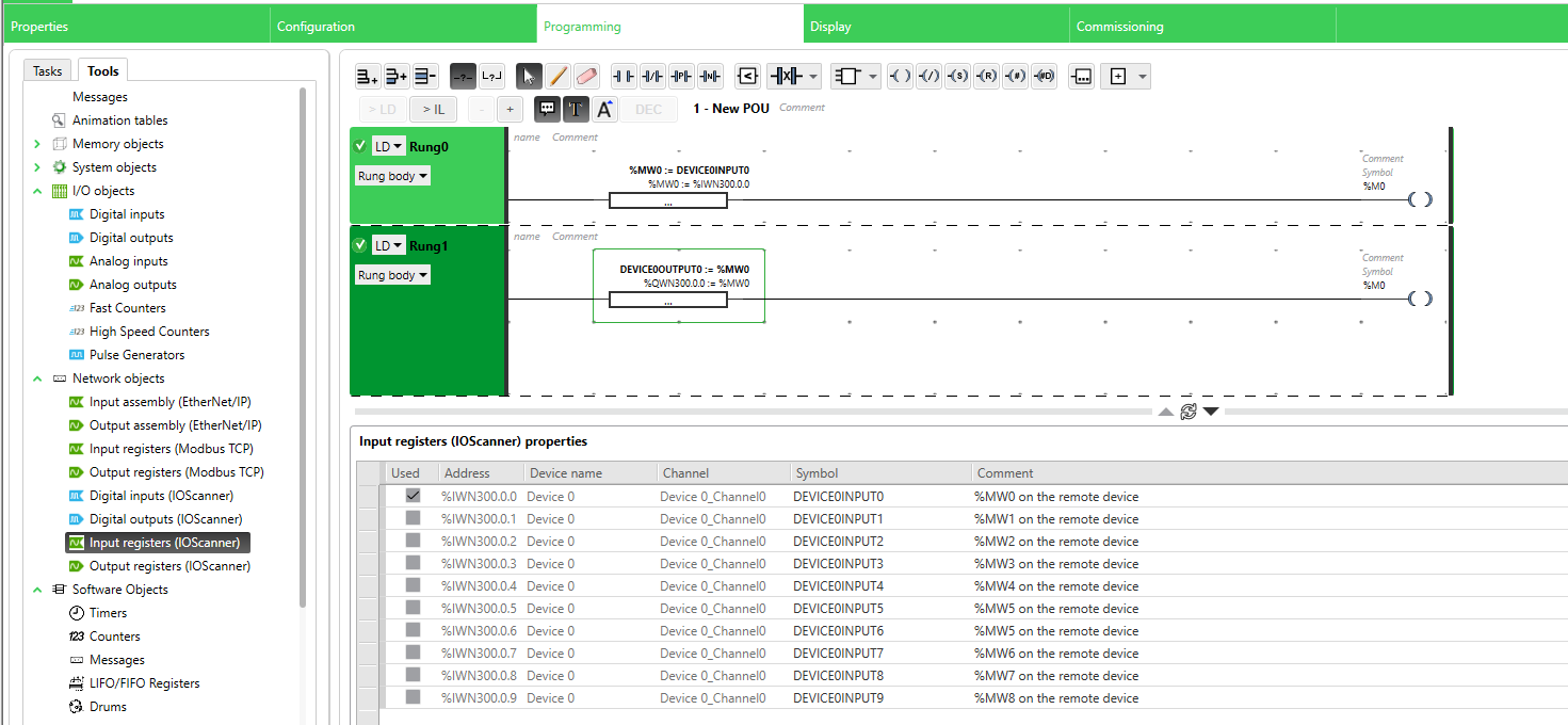
8) Under the Tools-> Network objects, select "Input registers (IOScanner)"
In this screen, we can see the Input registers represented as %IWN300.0.0 to %IWN300.0.9.
We can also assign a Symbol name (a.k.a. Variable name or Tag name) in the corresponding cell under the "SYMBOL" column to each 16-bit WORD address:
9) Conversely, if you click on Tools-> Network objects, select "Output registers (IOScanner)" and we can see that the Output Words have addresses %QWN300.0.0 to %QWN300.0.9:
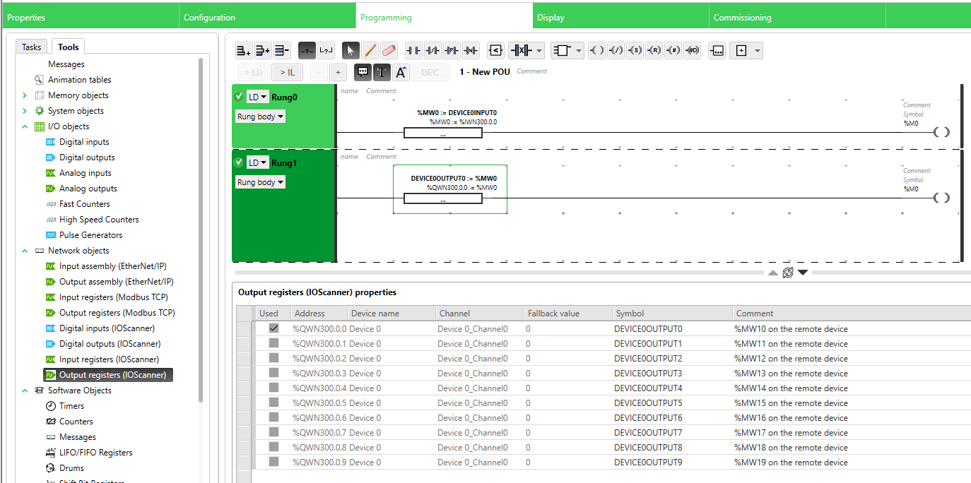
In the Example ladder logic two rungs above, we are getting the value from the Remote device’s Input Register 0 and writing it into the internal memory address %MW0, then writing it back to the Remote device’s Output Register 0.
The Input and Output Word addresses will always be in the format:
Outputs: %QWN30x.y.z
Inputs: %IWN30x.y.z
where:
x - Device Index (ID) Number from Step 4c above (you may have multiple Devices with the same IP Address)
y - Channel number ID (from Step 6 - each set of registers to read to or write from using the selected Modbus Function Code will have a unique Channel ID Number inside each defined Device)
z - Word address number - 0 would be the value from Offset address+0, 1 from Offset address+1, etc. (See Comments column in the screenshots for steps 8 and 9)
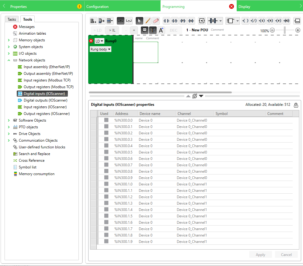
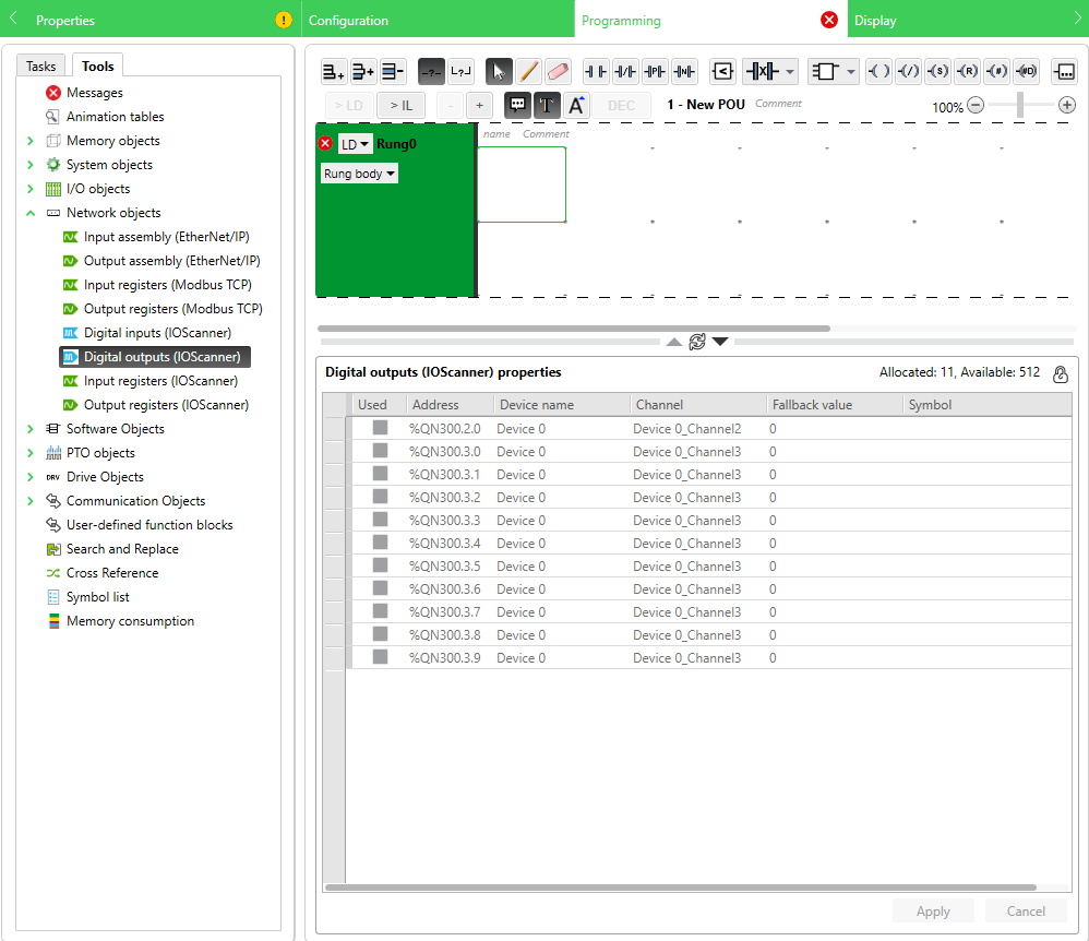
For Reading and Writing of Bits (with Function Codes 0x01, 0x02, 0x05, 0x0F):

The Input and Output Bit addresses will always be in the format (same as Words, except without the "W"):
Outputs: %QN30x.y.z
Inputs: %IN30x.y.z
where:
x - Device Index (ID) Number from Step 4c above (you may have multiple Devices with the same IP Address)
y - Channel number ID (from Step 6 - each set of registers to read to or write from using the selected Modbus Function Code will have a unique Channel ID Number inside each defined Device)
z - Bit address number - 0 would be the value from Offset address+0, 1 from Offset address+1, etc. (See Comments column in the screenshots for steps 8 and 9)
How do I configure the Modbus TCP IO Scanner for M221 and what addresses do we use to read and write from the remote device?
Product Line
EcoStruxure Machine Expert-Basic, SoMachine Basic, Modicon M221
Environment
PLC configuration software for Windows
Resolution
Follow the example steps below:
1) Go to the Configuration Tab in SoMachine Basic (or EcoStruxure Machine Expert-Basic)
2) Expand ETH1
3) Select Modbus TCP IOScanner
4) In the Modbus TCP area to the right,
(A) Tick the "Modbus TCP IOScanner" checkbox to Activate it
(B) Enter the IP Address of your remote Ethernet server - in our example, we are using 192.168.0.100
(C) Click Add - this will create a Device Row representing your device and a set of addresses to read to, write from, or both.
(D) Click on the [...] button under the "Channels" column
Clicking the [...] button will bring up the Channel Assistant screen:
5) In the Message Type dropdown, you can choose various Modbus function codes. Here are the supported Modbus function codes on the M221. We will use Function Code 23 (0x17) Read and Write registers:
6) In our example, we will keep it as Read/Write multiple words.
Let’s say we have a Remote I/O Device that has 10 Analog inputs at %MW0 to %MW9 and 10 Analog Outputs at %MW10 to %MW20, we would set up the offset and lengths accordingly:
7) Now, go to the Programming Tab on the top bar.
8) Under the Tools-> Network objects, select "Input registers (IOScanner)"
In this screen, we can see the Input registers represented as %IWN300.0.0 to %IWN300.0.9.
We can also assign a Symbol name (a.k.a. Variable name or Tag name) in the corresponding cell under the "SYMBOL" column to each 16-bit WORD address:
9) Conversely, if you click on Tools-> Network objects, select "Output registers (IOScanner)" and we can see that the Output Words have addresses %QWN300.0.0 to %QWN300.0.9:
In the Example ladder logic two rungs above, we are getting the value from the Remote device’s Input Register 0 and writing it into the internal memory address %MW0, then writing it back to the Remote device’s Output Register 0.
The Input and Output Word addresses will always be in the format:
Outputs: %QWN30x.y.z
Inputs: %IWN30x.y.z
where:
x - Device Index (ID) Number from Step 4c above (you may have multiple Devices with the same IP Address)
y - Channel number ID (from Step 6 - each set of registers to read to or write from using the selected Modbus Function Code will have a unique Channel ID Number inside each defined Device)
z - Word address number - 0 would be the value from Offset address+0, 1 from Offset address+1, etc. (See Comments column in the screenshots for steps 8 and 9)
For Reading and Writing of Bits (with Function Codes 0x01, 0x02, 0x05, 0x0F):
The Input and Output Bit addresses will always be in the format (same as Words, except without the "W"):
Outputs: %QN30x.y.z
Inputs: %IN30x.y.z
where:
x - Device Index (ID) Number from Step 4c above (you may have multiple Devices with the same IP Address)
y - Channel number ID (from Step 6 - each set of registers to read to or write from using the selected Modbus Function Code will have a unique Channel ID Number inside each defined Device)
z - Bit address number - 0 would be the value from Offset address+0, 1 from Offset address+1, etc. (See Comments column in the screenshots for steps 8 and 9)
Gepubliceerd voor:Schneider Electric Belgium


