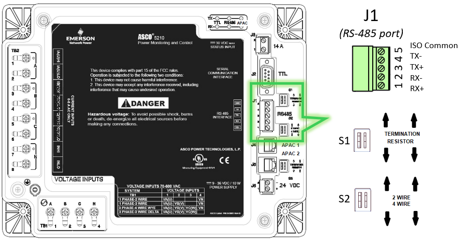
RS-485 Port and DIP SW Settings
1. On J1, terminate twisted pair cable.
2. Set proper termination for S1 (Terminating resistor).
2.1 Terminating resistor should be ON if 5210 is the last device on the loop.
2.2 Otherwise, it should be OFF.
3. Choose 2-wire or 4-wire (S2).
3.1. For 2-wire, connect on any + or - terminals. Moving the DIP SW will internally connect the terminal. No need for external jumper.
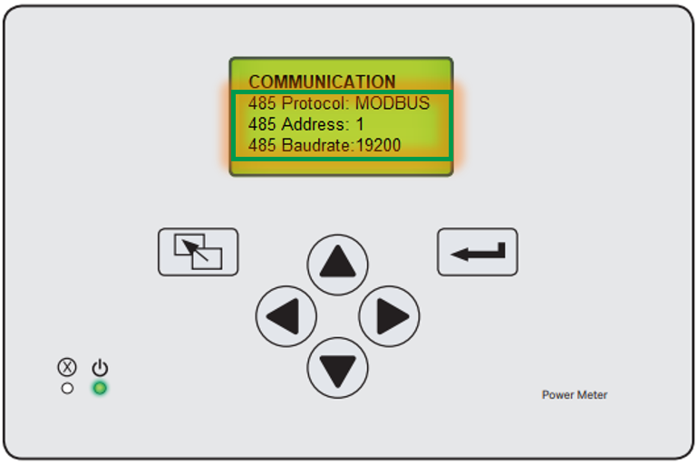
Serial Communication Settings on ASCO 5210 Power Meter
4. On 5210 PM, go to Main Menu ➡ Settings ➡ Communication ➡ 485 Protocol..
5. Set protocol to Modbus.
6. Set appropriate baud rate and device address.
Please refer to the attached Power Meter Modus Register Map document (381339-307D ) for holding register addresses.
You may also refer to the related video below for further information:
1. On J1, terminate twisted pair cable.
2. Set proper termination for S1 (Terminating resistor).
2.1 Terminating resistor should be ON if 5210 is the last device on the loop.
2.2 Otherwise, it should be OFF.
3. Choose 2-wire or 4-wire (S2).
3.1. For 2-wire, connect on any + or - terminals. Moving the DIP SW will internally connect the terminal. No need for external jumper.
Serial Communication Settings on ASCO 5210 Power Meter
4. On 5210 PM, go to Main Menu ➡ Settings ➡ Communication ➡ 485 Protocol..
5. Set protocol to Modbus.
6. Set appropriate baud rate and device address.
Please refer to the attached Power Meter Modus Register Map document (381339-307D ) for holding register addresses.
You may also refer to the related video below for further information:
Released for: Schneider Electric Singapore
