
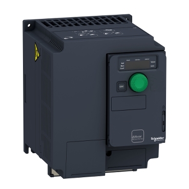


ATV320U40M3C
Network number of phases:
Motor power kW:


| Range of product | Altivar Machine ATV320 |
|---|---|
| Product or component type | Variable speed drive |
| Product specific application | Complex machines |
| Variant | Standard version |
| Format of the drive | Compact |
| Mounting mode | Wall mount |
| Communication port protocol | Modbus serial CANopen |
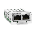
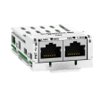
| Option card | Communication module, CANopen Communication module, EtherCAT Communication module, Profibus DP V1 Communication module, PROFINET Communication module, Ethernet Powerlink Communication module, EtherNet/IP Communication module, DeviceNet |
| [Us] rated supply voltage | 200...240 V - 15...10 % |
| Nominal output current | 17.5 A |
| Motor power kW | 4.0 kW for heavy duty |
| Motor power hp | 5 hp |
| EMC filter | Without EMC filter |
| IP degree of protection | IP20 |
| Discrete input number | 7 |
|---|---|
| Discrete input type | STO safe torque off, 24 V DC, impedance: 1.5 kOhm DI1...DI6 logic inputs, 24 V DC (30 V) DI5 programmable as pulse input: 0…30 kHz, 24 V DC (30 V) |
| Discrete input logic | Positive logic (source) Negative logic (sink) |
| Discrete output number | 3 |
| Discrete output type | Open collector DQ+ 0…1 kHz 30 V DC 100 mA Open collector DQ- 0…1 kHz 30 V DC 100 mA |
| Analogue input number | 3 |
| Analogue input type | AI1 voltage: 0...10 V DC, impedance: 30 kOhm, resolution 10 bits AI2 bipolar differential voltage: +/- 10 V DC, impedance: 30 kOhm, resolution 10 bits AI3 current: 0...20 mA (or 4-20 mA, x-20 mA, 20-x mA or other patterns by configuration), impedance: 250 Ohm, resolution 10 bits |
| Analogue output number | 1 |
| Analogue output type | Software-configurable current AQ1: 0...20 mA impedance 800 Ohm, resolution 10 bits Software-configurable voltage AQ1: 0...10 V DC impedance 470 Ohm, resolution 10 bits |
| Relay output type | Configurable relay logic R1A 1 NO electrical durability 100000 cycles Configurable relay logic R1B 1 NC electrical durability 100000 cycles Configurable relay logic R1C Configurable relay logic R2A 1 NO electrical durability 100000 cycles Configurable relay logic R2C |
| Maximum switching current | Relay output R1A, R1B, R1C on resistive load, cos phi = 1: 3 A at 250 V AC Relay output R1A, R1B, R1C on resistive load, cos phi = 1: 3 A at 30 V DC Relay output R1A, R1B, R1C, R2A, R2C on inductive load, cos phi = 0.4 and L/R = 7 ms: 2 A at 250 V AC Relay output R1A, R1B, R1C, R2A, R2C on inductive load, cos phi = 0.4 and L/R = 7 ms: 2 A at 30 V DC Relay output R2A, R2C on resistive load, cos phi = 1: 5 A at 250 V AC Relay output R2A, R2C on resistive load, cos phi = 1: 5 A at 30 V DC |
| Minimum switching current | Relay output R1A, R1B, R1C, R2A, R2C: 5 mA at 24 V DC |
| Method of access | Slave CANopen |
| 4 quadrant operation possible | True |
| Asynchronous motor control profile | Voltage/frequency ratio, 5 points Flux vector control without sensor, standard Voltage/frequency ratio - Energy Saving, quadratic U/f Flux vector control without sensor - Energy Saving Voltage/frequency ratio, 2 points |
| Synchronous motor control profile | Vector control without sensor |
| Maximum output frequency | 0.599 kHz |
| Acceleration and deceleration ramps | Linear U S CUS Ramp switching Acceleration/deceleration ramp adaptation Acceleration/deceleration automatic stop with DC injection |
| Motor slip compensation | Automatic whatever the load Adjustable 0...300 % Not available in voltage/frequency ratio (2 or 5 points) |
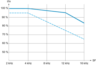
| Switching frequency | 2...16 kHz adjustable 4...16 kHz with derating factor |
| Nominal switching frequency | 4 kHz |
| Braking to standstill | By DC injection |
| Brake chopper integrated | True |
| Line current | 23.8 A at 200 V (heavy duty) 19.9 A at 240 V (heavy duty) |
| Maximum input current | 23.8 A |
| Maximum output voltage | 240 V |
| Apparent power | 8.3 kVA at 240 V (heavy duty) |
| Network frequency | 50...60 Hz |
| Relative symmetric network frequency tolerance | 5 % |
| Prospective line Isc | 5 kA |
| Base load current at high overload | 17.0 A |
| Power dissipation in W | Fan: 140 W at 200 V, switching frequency 4 kHz |
| With safety function Safely Limited Speed (SLS) | True |
| With safety function Safe brake management (SBC/SBT) | False |
| With safety function Safe Operating Stop (SOS) | False |
| With safety function Safe Position (SP) | False |
| With safety function Safe programmable logic | False |
| With safety function Safe Speed Monitor (SSM) | False |
| With safety function Safe Stop 1 (SS1) | True |
| With sft fct Safe Stop 2 (SS2) | False |
| With safety function Safe torque off (STO) | True |
| With safety function Safely Limited Position (SLP) | False |
| With safety function Safe Direction (SDI) | False |
| Protection type | Input phase breaks: drive Overcurrent between output phases and earth: drive Overheating protection: drive Short-circuit between motor phases: drive Thermal protection: drive |
| Width | 140 mm |
| Height | 184.0 mm |
| Depth | 158.0 mm |
| Net weight | 2.2 kg |
| Transient overtorque | 170…200 % of nominal motor torque |
| Operating position | Vertical +/- 10 degree |
|---|---|
| Product certifications | CE ATEX NOM GOST EAC RCM KC |
| Marking | CE ATEX UL CSA EAC RCM |
| Standards | IEC 61800-5-1 |
| Electromagnetic compatibility | Electrostatic discharge immunity test level 3 conforming to IEC 61000-4-2 Radiated radio-frequency electromagnetic field immunity test level 3 conforming to IEC 61000-4-3 Electrical fast transient/burst immunity test level 4 conforming to IEC 61000-4-4 1.2/50 µs - 8/20 µs surge immunity test level 3 conforming to IEC 61000-4-5 Conducted radio-frequency immunity test level 3 conforming to IEC 61000-4-6 Voltage dips and interruptions immunity test conforming to IEC 61000-4-11 |
| Environmental class (during operation) | Class 3C3 according to IEC 60721-3-3 Class 3S2 according to IEC 60721-3-3 |
| Maximum acceleration under shock impact (during operation) | 150 m/s² at 11 ms |
| Maximum acceleration under vibrational stress (during operation) | 10 m/s² at 13...200 Hz |
| Maximum deflection under vibratory load (during operation) | 1.5 mm at 2...13 Hz |
| Permitted relative humidity (during operation) | Class 3K5 according to EN 60721-3 |
| Volume of cooling air | 16.4 m3/h |
| Overvoltage category | III |
| Regulation loop | Adjustable PID regulator |
| Speed accuracy | +/- 10 % of nominal slip 0.2 Tn to Tn |
| Pollution degree | 2 |
| Ambient air transport temperature | -25…70 °C |
| Ambient air temperature for operation | -10…50 °C without derating 50…60 °C with derating factor |
| Ambient air temperature for storage | -25…70 °C |
| Unit Type of Package 1 | PCE |
|---|---|
| Number of Units in Package 1 | 1 |
| Package 1 Height | 24.500 cm |
| Package 1 Width | 19.000 cm |
| Package 1 Length | 26.800 cm |
| Package 1 Weight | 2.562 kg |
| Unit Type of Package 2 | S06 |
| Number of Units in Package 2 | 12 |
| Package 2 Height | 75.000 cm |
| Package 2 Width | 60.000 cm |
| Package 2 Length | 80.000 cm |
| Package 2 Weight | 44.260 kg |


Only Possible at Ambient Temperature Less or Equal to 50 °C (122 °F)


For Operation at Ambient Temperature Above 50 °C (122 °F)

(1) Line choke (if used)
(2) Use relay output R1 set to operating state Fault to switch Off the product once an error is detected.

(1) Line choke (if used)
(2) Use relay output R1 set to operating state Fault to switch Off the product once an error is detected.

(1) Analog output
(2) Analog inputs
(3) Potentiometer SZ1RV1202 (2.2 kΩ) or similar (10 kΩ maximum)
(4) Digital Inputs - Shielding instructions are given in the Electromagnetic Compatibility section
Switch Set to SRC (Source) Position Using the Output Power Supply for the Digital Inputs

Switch Set to SRC (Source) Position and Use of an External Power Supply for the Digital Inputs

Switch Set to SK (Sink) Position Using the Output Power Supply for the Digital Inputs

Switch Set to EXT Position Using an External Power Supply for the Digital Inputs

NOTE :
• STO input is also connected by default on a 24 Vdc terminal. If the external power supply is switched off, the function STO will be triggered.
• To avoid triggering the STO function when switching-on the product, the external power supply must be previously switched on.
 40 °C (104 °F) - Mounting type A, B and C
 50 °C (122 °F) - Mounting type C
 60 °C (140 °F) - Mounting type C
In : Nominal Drive Current
SF : Switching Frequency
Items usually bought together


Need more information? Check our technical FAQs!
Easily find answers to the most frequently asked questions.