
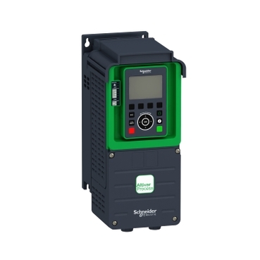


ATV930U22N4


| Range of product | Altivar Process ATV900 |
|---|---|
| Product specific application | Process for industrial |
| Product or component type | Variable speed drive |
| Variant | Standard version With braking chopper |
| Device application | Industrial application |
| Product destination | Synchronous motors Asynchronous motors |
| Network number of phases | 3 phases |
| Mounting mode | Wall mount |
| Continuous output current | 5.6 A at 4 kHz for normal duty 4 A at 4 kHz for heavy duty |
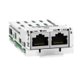
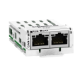
| Communication port protocol | Modbus TCP EtherNet/IP Modbus serial |
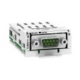
| option module | Slot A: communication module for Profibus DP V1 Slot A: communication module for PROFINET Slot A: communication module for DeviceNet Slot A: communication module for EtherCAT Slot A: communication module for CANopen daisy chain RJ45 Slot A: communication module for CANopen SUB-D 9 Slot A: communication module for CANopen screw terminals Slot A/slot B/slot C: digital and analog I/O extension module Slot A/slot B/slot C: output relay extension module Slot B: 5/12 V digital encoder interface module Slot B: analog encoder interface module Slot B: resolver encoder interface module communication module for Ethernet Powerlink |
| [Us] rated supply voltage | 380...480 V - 15...10 % |
| [Us] rated supply voltage | 380...480 V |
| Relative symmetric mains voltage tolerance | 10 % |
| Relative symmetric network frequency tolerance | 5 % |
| Nominal output current | 5.6 A |
| Motor power kW | 2.2 kW for normal duty 1.5 kW for heavy duty |
| EMC filter | Integrated With EMC plate option |
| IP degree of protection | IP21 |
| Degree of protection | UL type 1 |
| Electrical connection | Control: screw terminal 0.5...1.5 mm²/AWG 20...AWG 16 Line side: screw terminal 2.5...6 mm²/AWG 14...AWG 10 Motor: screw terminal 2.5...6 mm²/AWG 14...AWG 10 DC bus: screw terminal 2.5...6 mm²/AWG 14...AWG 10 |
|---|---|
| Transmission rate | 10/100 Mbit/s for Ethernet IP/Modbus TCP 4.8, 9.6, 19.2, 38.4 kbit/s for Modbus serial |
| Exchange mode | Half duplex, full duplex, autonegotiation Ethernet IP/Modbus TCP |
| Data format | 8 bits, configurable odd, even or no parity for Modbus serial |
| Type of polarization | No impedance for Modbus serial |
| Number of addresses | 1…247 for Modbus serial |
| Supply | External supply for digital inputs: 24 V DC (19…30 V), <1.25 mA, protection type: overload and short-circuit protection Internal supply for reference potentiometer (1 to 10 kOhm): 10.5 V DC +/- 5 %, <10 mA, protection type: overload and short-circuit protection Internal supply for digital inputs and STO: 24 V DC (21…27 V), <200 mA, protection type: overload and short-circuit protection |
| Local signalling | Local diagnostic: 3 LED (mono/dual colour) Embedded communication status: 5 LED (dual colour) Communication module status: 2 LED (dual colour) Presence of voltage: 1 LED (red) |
| Input compatibility | DI1...DI8: discrete input level 1 PLC conforming to IEC 61131-2 DI7, DI8: pulse input level 1 PLC conforming to IEC 65A-68 STOA, STOB: discrete input level 1 PLC conforming to IEC 61131-2 |
| Discrete input logic | Positive logic (source) (DI1...DI8), < 5 V (state 0), > 11 V (state 1) Negative logic (sink) (DI1...DI8), > 16 V (state 0), < 10 V (state 1) Positive logic (source) (DI7, DI8), < 0.6 V (state 0), > 2.5 V (state 1) Positive logic (source) (STOA, STOB), < 5 V (state 0), > 11 V (state 1) |
| Sampling duration | 2 ms +/- 0.5 ms (DI1...DI8) - discrete input 5 ms +/- 1 ms (DI7, DI8) - pulse input 1 ms +/- 1 ms (AI1, AI2, AI3) - analog input 5 ms +/- 1 ms (AQ1, AQ2) - analog output |
| Accuracy | +/- 0.6 % AI1, AI2, AI3 for a temperature variation 60 °C analog input +/- 1 % AQ1, AQ2 for a temperature variation 60 °C analog output |
| Linearity error | AI1, AI2, AI3: +/- 0.15 % of maximum value for analog input AQ1, AQ2: +/- 0.2 % for analog output |
| Refresh time | Relay output (R1, R2, R3): 5 ms (+/- 0.5 ms) |
| Isolation | Between power and control terminals |
| Discrete input number | 10 |
| Discrete input type | DI1...DI8 programmable, 24 V DC (<= 30 V), impedance: 3.5 kOhm DI7, DI8 programmable as pulse input: 0…30 kHz, 24 V DC (<= 30 V) STOA, STOB safe torque off, 24 V DC (<= 30 V), impedance: > 2.2 kOhm |
| Discrete input logic | 16 preset speeds |
| Discrete output number | 2 |
| Discrete output type | Logic output DQ+ 0…1 kHz <= 30 V DC 100 mA Programmable as pulse output DQ+ 0…30 kHz <= 30 V DC 20 mA Logic output DQ- 0…1 kHz <= 30 V DC 100 mA |
| Analogue input number | 3 |
| Analogue input type | AI1, AI2, AI3 software-configurable voltage: 0...10 V DC, impedance: 30 kOhm, resolution 12 bits AI1, AI2, AI3 software-configurable current: 0...20 mA/4...20 mA, impedance: 250 Ohm, resolution 12 bits |
| Analogue output number | 2 |
| Analogue output type | Software-configurable voltage AQ1, AQ2: 0...10 V DC impedance 470 Ohm, resolution 10 bits Software-configurable current AQ1, AQ2: 0...20 mA impedance 500 Ohm, resolution 10 bits |
| Relay output number | 3 |
| Relay output type | Configurable relay logic R1: fault relay NO/NC electrical durability 100000 cycles Configurable relay logic R2: sequence relay NO electrical durability 1000000 cycles Configurable relay logic R3: sequence relay NO electrical durability 1000000 cycles |
| Maximum switching current | Relay output R1 on resistive load, cos phi = 1: 3 A at 250 V AC Relay output R1 on resistive load, cos phi = 1: 3 A at 30 V DC Relay output R1 on inductive load, cos phi = 0.4 and L/R = 7 ms: 2 A at 250 V AC Relay output R1 on inductive load, cos phi = 0.4 and L/R = 7 ms: 2 A at 30 V DC Relay output R2, R3 on resistive load, cos phi = 1: 5 A at 250 V AC Relay output R2, R3 on resistive load, cos phi = 1: 5 A at 30 V DC Relay output R2, R3 on inductive load, cos phi = 0.4 and L/R = 7 ms: 2 A at 250 V AC Relay output R2, R3 on inductive load, cos phi = 0.4 and L/R = 7 ms: 2 A at 30 V DC |
| Minimum switching current | Relay output R1, R2, R3: 5 mA at 24 V DC |
| Physical interface | Ethernet 2-wire RS 485 |
| Connector type | 2 RJ45 1 RJ45 |
| Method of access | Slave Modbus TCP |
| Transmission rate | 10, 100 Mbits 4.8 kbps 9600 bit/s 19200 bit/s |
| Transmission frame | RTU |
| Number of addresses | 1…247 |
| Data format | 8 bits, configurable odd, even or no parity |
| Type of polarization | No impedance |
| 4 quadrant operation possible | True |
| Asynchronous motor control profile | Constant torque standard Optimized torque mode Variable torque standard |
| Synchronous motor control profile | Permanent magnet motor Synchronous reluctance motor |
| Maximum output frequency | 599 Hz |
| Acceleration and deceleration ramps | Linear adjustable separately from 0.01...9999 s |
| Motor slip compensation | Can be suppressed Not available in permanent magnet motor law Adjustable Automatic whatever the load |
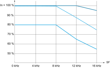
| Switching frequency | 2...16 kHz adjustable 4...16 kHz with derating factor |
| Nominal switching frequency | 4 kHz |
| Braking to standstill | By DC injection |
| Brake chopper integrated | True |
| Line current | 4.3 A at 380 V (normal duty) 3.1 A at 380 V (heavy duty) 3.8 A at 480 V (normal duty) 2.9 A at 480 V (heavy duty) |
| Maximum input current | 4.3 A |
| Maximum output voltage | 480.0 V |
| Apparent power | 3.2 kVA at 480 V (normal duty) 2.4 kVA at 480 V (heavy duty) |
| Maximum transient current | 6.7 A during 60 s (normal duty) 6 A during 60 s (heavy duty) |
| Network frequency | 50...60 Hz |
| Prospective line Isc | 50 kA |
| Base load current at high overload | 4.0 A |
| Base load current at low overload | 5.6 A |
| Power dissipation in W | Natural convection: 30 W at 380 V, switching frequency 4 kHz Forced convection: 60 W at 380 V, switching frequency 4 kHz |
| With safety function Safely Limited Speed (SLS) | True |
| With safety function Safe brake management (SBC/SBT) | True |
| With safety function Safe Operating Stop (SOS) | False |
| With safety function Safe Position (SP) | False |
| With safety function Safe programmable logic | False |
| With safety function Safe Speed Monitor (SSM) | False |
| With safety function Safe Stop 1 (SS1) | True |
| With sft fct Safe Stop 2 (SS2) | False |
| With safety function Safe torque off (STO) | True |
| With safety function Safely Limited Position (SLP) | False |
| With safety function Safe Direction (SDI) | False |
| Protection type | Thermal protection: motor Safe torque off: motor Motor phase break: motor Thermal protection: drive Safe torque off: drive Overheating: drive Overcurrent between output phases and earth: drive Overload of output voltage: drive Short-circuit protection: drive Motor phase break: drive Overvoltages on the DC bus: drive Line supply overvoltage: drive Line supply undervoltage: drive Line supply phase loss: drive Overspeed: drive Break on the control circuit: drive |
| Quantity per set | 1 |
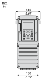
| Width | 144 mm |
| Height | 350 mm |
| Depth | 206 mm |
| Net weight | 4.5 kg |
| Insulation resistance | > 1 MOhm 500 V DC for 1 minute to earth |
|---|---|
| Noise level | 54.5 dB conforming to 86/188/EEC |
| Vibration resistance | 1.5 mm peak to peak (f= 2…13 Hz) conforming to IEC 60068-2-6 1 gn (f= 13…200 Hz) conforming to IEC 60068-2-6 |
| Shock resistance | 15 gn for 11 ms conforming to IEC 60068-2-27 |
| Environmental characteristic | Chemical pollution resistance class 3C3 conforming to IEC 60721-3-3 Dust pollution resistance class 3S3 conforming to IEC 60721-3-3 |
| Relative humidity | 5…95 % without condensation conforming to IEC 60068-2-3 |
| Ambient air temperature for operation | -15…50 °C (without derating) 50…60 °C (with derating factor) |
| Operating altitude | <= 1000 m without derating 1000...4800 m with current derating 1 % per 100 m |
| Operating position | Vertical +/- 10 degree |
| Product certifications | CSA UL TÜV |
| Marking | CE |
| Standards | UL 508C IEC 61800-3 IEC 61800-5-1 IEC 61000-3-12 IEC 60721-3 IEC 61508 IEC 13849-1 |
| Maximum THDI | <48 % full load conforming to IEC 61000-3-12 |
| Assembly style | Enclosed |
| Electromagnetic compatibility | Electrostatic discharge immunity test level 3 conforming to IEC 61000-4-2 Radiated radio-frequency electromagnetic field immunity test level 3 conforming to IEC 61000-4-3 Electrical fast transient/burst immunity test level 4 conforming to IEC 61000-4-4 1.2/50 µs - 8/20 µs surge immunity test level 3 conforming to IEC 61000-4-5 Conducted radio-frequency immunity test level 3 conforming to IEC 61000-4-6 |
| Environmental class (during operation) | Class 3C3 according to IEC 60721-3-3 Class 3S3 according to IEC 60721-3-3 |
| Maximum acceleration under shock impact (during operation) | 150 m/s² at 11 ms |
| Maximum acceleration under vibrational stress (during operation) | 10 m/s² at 13...200 Hz |
| Maximum deflection under vibratory load (during operation) | 1.5 mm at 2...13 Hz |
| Permitted relative humidity (during operation) | Class 3K5 according to EN 60721-3 |
| Volume of cooling air | 38 m3/h |
| Overvoltage category | III |
| Regulation loop | Adjustable PID regulator |
| Noise level | 54.5 dB |
| Pollution degree | 2 |
| Ambient air transport temperature | -40…70 °C |
| Ambient air temperature for storage | -40…70 °C |
| Unit Type of Package 1 | PCE |
|---|---|
| Number of Units in Package 1 | 1 |
| Package 1 Height | 31.000 cm |
| Package 1 Width | 19.000 cm |
| Package 1 Length | 41.000 cm |
| Package 1 Weight | 6.016 kg |
| Unit Type of Package 2 | S06 |
| Number of Units in Package 2 | 6 |
| Package 2 Height | 75.000 cm |
| Package 2 Width | 60.000 cm |
| Package 2 Length | 80.000 cm |
| Package 2 Weight | 49.120 kg |
Right, Front and Rear View


X1 | X2 | X3 |
|---|---|---|
≥ 100 mm (3.94 in.) | ≥ 100 mm (3.94 in.) | ≥ 10 mm (0.39 in.) |
Mount the device in a vertical position (±10°). This is required for cooling the device.
Do not mount the device close to heat sources.
Leave sufficient free space so that the air required for cooling purposes can circulate from the bottom to the top of the drive.

a ≥ 100 mm (3.94 in.)


a ≥ 0
Connection diagrams conforming to standards EN 954-1 category 1 and IEC/EN 61508 capacity SIL1, stopping category 0 in accordance with standard IEC/EN 60204-1

(1) Line choke if used
(2) Use relay R1 set to operating state Fault to switch Off the product once an error is detected.
A1 : Drive
KM1 : Line Contactor
Q2, Q3 : Circuit breakers
S1, S2 : Pushbuttons
T1 : Transformer for control part
Connection diagrams conforming to standards EN 954-1 category 1 and IEC/EN 61508 capacity SIL1, stopping category 0 in accordance with standard IEC/EN 60204-1

(1) Line choke if used
(2) Use relay R1 set to operating state Fault to switch Off the product once an error is detected.
A1 : Drive
KM1 : Contactor

(1) Safe Torque Off
(2) Analog Output
(3) Digital Input
(4) Reference potentiometer
(5) Analog Input
(6) Digital Output
(7) 0-10 Vdc, x-20 mA
(8) 0-10 Vdc, -10 Vdc...+10 Vdc
R1A, R1B, R1C : Fault relay
R2A, R2C : Sequence relay
R3A, R3C : Sequence relay

It is possible to connect either 1 or 3 sensors on terminals AI1 or AI3
The switch is used to adapt the operation of the logic inputs to the technology of the programmable controller outputs.
Set the switch to Source (factory setting) if using PLC outputs with PNP transistors.
Set the switch to Ext if using PLC outputs with NPN transistors.


 40 °C (104 °F) - Mounting type A, B and C
 50 °C (122 °F) - Mounting type A, B and C
 60 °C (140 °F) - Mounting type B and C
In : Nominal Drive Current
SF : Switching Frequency
Items usually bought together


Need more information? Check our technical FAQs!
Easily find answers to the most frequently asked questions.