
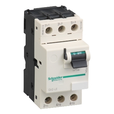


GV2LE06
[In] rated current:


| Range | TeSys Deca |
|---|---|
| Product name | TeSys GV2 |
| Product or component type | Motor circuit breaker |
| Device short name | GV2LE |
| Device application | Motor protection |
| Trip unit technology | Magnetic |
| Poles description | 3P |
|---|---|
| Network type | AC |
| Utilisation category | Category A conforming to IEC 60947-2 AC-3 conforming to IEC 60947-4-1 AC-3e conforming to IEC 60947-4-1 |
| Network frequency | 50/60 Hz conforming to IEC 60947-2 |
| Motor power kW | 0.55 kW at 400/415 V AC 50/60 Hz 0.55 kW at 500 V AC 50/60 Hz 0.75 kW at 500 V AC 50/60 Hz 1.1 kW at 690 V AC 50/60 Hz |
| Breaking capacity | 100 kA Icu at 230/240 V AC 50/60 Hz conforming to IEC 60947-2 100 kA Icu at 400/415 V AC 50/60 Hz conforming to IEC 60947-2 100 kA Icu at 440 V AC 50/60 Hz conforming to IEC 60947-2 100 kA Icu at 500 V AC 50/60 Hz conforming to IEC 60947-2 100 kA Icu at 690 V AC 50/60 Hz conforming to IEC 60947-2 |
| [Ics] rated service short-circuit breaking capacity | 100 % at 230/240 V AC 50/60 Hz conforming to IEC 60947-2 100 % at 400/415 V AC 50/60 Hz conforming to IEC 60947-2 100 % at 440 V AC 50/60 Hz conforming to IEC 60947-2 100 % at 500 V AC 50/60 Hz conforming to IEC 60947-2 100 % at 690 V AC 50/60 Hz conforming to IEC 60947-2 |
| Control type | Toggle |
| [In] rated current | 1.6 A |
| Magnetic tripping current | 26.2 A |
| [Ith] conventional free air thermal current | 1.6 A conforming to IEC 60947-2 |
| [Ue] rated operational voltage | 690 V AC 50/60 Hz conforming to IEC 60947-2 |
| [Ui] rated insulation voltage | 690 V AC 50/60 Hz conforming to IEC 60947-2 |
| [Uimp] rated impulse withstand voltage | 6 kV conforming to IEC 60947-2 |
| Suitability for isolation | Yes conforming to IEC 60947-1 |
| Power dissipation per pole | 1.8 W |
| Mechanical durability | 100000 cycles |
| Electrical durability | 100000 cycles for AC-3 at 415 V In 100000 cycles for AC-3e at 415 V In |
| Rated duty | Uninterrupted conforming to IEC 60947-4-1 |
| Connections - terminals | Power circuit: screw clamp terminal 2 cable(s) 1…6 mm²solid Power circuit: screw clamp terminal 2 cable(s) 1.5…6 mm²flexible without cable end Power circuit: screw clamp terminal 2 cable(s) 1…4 mm²flexible with cable end |
| Tightening torque | 1.7 N.m - on screw clamp terminal |
| Fixing mode | 35 mm symmetrical DIN rail: clipped Panel: screwed (with adaptor plate) |
| Mounting position | Horizontal Vertical |
| Width | 45 mm |
| Height | 89 mm |
| Depth | 78.5 mm |
| Net weight | 0.33 kg |
| Colour | Dark grey |
| Standards | EN/IEC 60947-2 EN/IEC 60947-4-1 UL 60947-4-1 CSA C22.2 No 60947-4-1 IEC/EN 60335-2-40:Annex JJ |
|---|---|
| Product certifications | CCC UL CSA EAC LROS (Lloyds register of shipping) BV RINA DNV-GL UKCA IECEE CB Scheme |
| IK degree of protection | IK04 |
| IP degree of protection | IP20 conforming to IEC 60529 |
| Climatic withstand | conforming to IACS E10 |
| Ambient air temperature for storage | -40…80 °C |
| Fire resistance | 960 °C conforming to IEC 60695-2-11 |
| Ambient air temperature for operation | -20…60 °C |
| Mechanical robustness | Shocks: 30 Gn for 11 ms Vibrations: 5 Gn, 5...150 Hz |
| Operating altitude | <= 2000 m |
| Unit Type of Package 1 | PCE |
|---|---|
| Number of Units in Package 1 | 1 |
| Package 1 Height | 8.5 cm |
| Package 1 Width | 9.2 cm |
| Package 1 Length | 4.8 cm |
| Package 1 Weight | 245.0 g |
| Unit Type of Package 2 | S02 |
| Number of Units in Package 2 | 24 |
| Package 2 Height | 15 cm |
| Package 2 Width | 30 cm |
| Package 2 Length | 40 cm |
| Package 2 Weight | 6.189 kg |
| Warranty | 12 months |
|---|
Average Operating Times at 20 °C Related to Multiples of the Setting Current

Dynamic Stress
I peak = f (prospective Isc) at 1.05 Ue = 435 V

Dynamic Stress
I peak = f (prospective Isc) at 1.05 Ue = 435 V

Thermal Limit in kA2s in the Magnetic Operating Zone
Sum of I2dt = f (prospective Isc) at 1.05 Ue = 435 V
Thermal Limit in kA2s in the Magnetic Operating Zone
Sum of I2dt = f (prospective Isc) at 1.05 Ue = 435 V

Dimensions
X1 Electrical clearance = 40 mm for Ue ≤ 690 V.
GVAD, AM, AN, AU, AS
GVAE
Mounting
On 35 mm rail

c = 80 on AM1 DP200 (35 x 7.5) and 88 on AM1 DE200, ED200 (35 x15)
On panel with adapter plate GV2 AF02
On pre-slotted plate AM1 PA
On rails DZ5 MB201
Mounting of External Operator GV2AP03 for GV2LE
Door cut-out
GV2L and GV2LE
Sets of busbars GV2G445, GV2G454, GV2G472, with terminal block GV2G05

l | p | |
|---|---|---|
GV2G445 (4 x 45 mm) | 179 | 45 |
GV2G454 (4 x 54 mm) | 206 | 54 |
GV2G472 (4 x 72 mm) | 260 | 72 |
Number of tap-offs | a | |||
|---|---|---|---|---|
5 | 6 | 7 | 8 | |
GV2G445 | 224 | 269 | 314 | 359 |
GV2G454 | 260 | 314 | 368 | 422 |
GV2G472 | 332 | 404 | 476 | 548 |
Sets of Busbars for GV2L and GV2LE
Sets of busbars GV2G●●● with terminal block GV1G09

Sets of busbars GV2G245, GV2G254, GV2GR272

I | |
|---|---|
GV2G245 (2 x 45 mm) | 89 |
GV2G254 (2 x 54 mm) | 98 |
GV2G272 (2 x 72 mm) | 116 |
Set of busbars GV2G554

Sets of busbars GV2G345 and GV2G354

I | |
|---|---|
GV2G345 (3 x 45 mm) | 134 |
GV2G354 (3 x 54 mm) | 152 |
GV2LE••
Items usually bought together

Need more information? Check our technical FAQs!
Easily find answers to the most frequently asked questions.