
Roll over image to zoom in


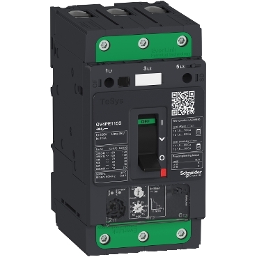
GV4PE115S
Environmental Data
Total lifecycle Carbon footprint
90
Use Better
Packaging made with recycled cardboard
Yes
Use Again
Recyclability potential, in %
49
Take-back
No


TeSys GV motor circuit breaker, 3 poles (3P), 115A/690V, for protection of 3-phase motors 37-55kW@400V. It provides thermal magnetic protection and additional motor protection functions, breaking capacity Icu 100kA@400V, start-stop control by toggle, connection by Everlink BTR screw terminals. Thermal protection adjustable by dials with a setting current Ir in range 65-115A and a selectable tripping class 10 or 20, magnetic protection at 17 In. Additional protections have fixed pick-up and include short time delay protection Isd at 13 Ir, phase unbalance and loss protection, ground fault protection. It makes internal locations available for additional auxiliary contact blocks (OF, SD), and voltage trip units (MN, MX). Multi standards certified (IEC, UL, CSA, CCC, EAC, Marine, ATEX), Green Premium compliant (RoHS/REACh).
| Range of product | TeSys GV4 |
|---|---|
| Range | TeSys Deca |
| Device short name | GV4PE |
| Product name | TeSys GV4 |
| Product or component type | Motor circuit breaker |
| Device application | Motor protection |
| Trip unit technology | Thermal-magnetic Electronic |
| Poles description | 3P |
|---|---|
| Utilisation category | Category A conforming to IEC 60947-2 AC-3 conforming to IEC 60947-4-1 |
| Operating position | Any position |
| Motor power kW | 37 kW at 400...415 V AC 50/60 Hz 45 kW at 400...415 V AC 50/60 Hz 55 kW at 400...415 V AC 50/60 Hz 45 kW at 500 V AC 50/60 Hz 55 kW at 500 V AC 50/60 Hz 75 kW at 500 V AC 50/60 Hz 75 kW at 660...690 V AC 50/60 Hz 90 kW at 660...690 V AC 50/60 Hz 110 kW at 660...690 V AC 50/60 Hz |
| Breaking capacity | 120 kA Icu at 220...240 V AC 50/60 Hz conforming to IEC 60947-2 100 kA Icu at 380...415 V AC 50/60 Hz conforming to IEC 60947-2 70 kA Icu at 440 V AC 50/60 Hz conforming to IEC 60947-2 30 kA Icu at 500 V AC 50/60 Hz conforming to IEC 60947-2 18 kA Icu at 525 V AC 50/60 Hz conforming to IEC 60947-2 100 kA at 208Y/120 V AC 50/60 Hz conforming to UL 60947 100 kA at 240 V AC 50/60 Hz conforming to UL 60947 65 kA at 480Y/277 V AC 50/60 Hz conforming to UL 60947 10 kA Icu at 660...690 V AC 50/60 Hz conforming to IEC 60947-2 25 kA at 600Y/347 V AC 50/60 Hz conforming to UL 60947 |
| Control type | Toggle |
| [In] rated current | 115 A |
| Magnetic tripping current | 1955 A |
| [Ue] rated operational voltage | 690 V AC 50/60 Hz conforming to IEC 60947-2 |
| [Ui] rated insulation voltage | 800 V AC 50/60 Hz conforming to IEC 60947-2 |
| [Ith] conventional free air thermal current | 115 A conforming to IEC 60947-4-1 |
| [Uimp] rated impulse withstand voltage | 8 kV conforming to IEC 60947-2 |
| Power dissipation per pole | 4.6 W |
| Mechanical durability | 40000 cycles |
| Electrical durability | 10000 cycles for AC-3 at 440 V In/2 5000 cycles for AC-3 at 440 V In |
| maximum operating rate | 25 cyc/h |
| Rated duty | Continuous conforming to IEC 60947-4-1 |
| Connections - terminals | EverLink BTR screw connectors (top) 1 cable(s) 1.5…70 mm² - solid EverLink BTR screw connectors (top) 1 cable(s) 1.5…50 mm² - flexible EverLink BTR screw connectors (bottom) 1 cable(s) 2.5…95 mm² - solid EverLink BTR screw connectors (bottom) 1 cable(s) 2.5…70 mm² - flexible |
| Tightening torque | 9 N.m for cable 16…95 mm² 5 N.m for cable 1.5…10 mm² |
| Mechanical robustness | Vibrations: +/- 1 mm 2...13.2 Hz conforming to IEC 60068-2-6 Vibrations: 0.7 gn 13.2...100 Hz conforming to IEC 60068-2-6 Shocks: 15 gn 11 ms conforming to IEC 60068-2-27 |
| Phase failure sensitivity | Yes conforming to IEC 60947-4-1 |
| Height | 155 mm |
| Width | 81 mm |
| Depth | 116 mm |
| Net weight | 1.45 kg |
| Colour | Grey (RAL 7016) |
| Suitability for isolation | Yes conforming to IEC 60947-1 |
| Standards | CSA C22.2 No 60947-4-1 UL 60947-4-1 EN/IEC 60947-4-1 EN/IEC 60947-2 |
|---|---|
| Product certifications | IEC UL CSA CCC EAC ATEX EU-RO MR |
| Climatic withstand | conforming to IACS E10 |
| IK degree of protection | IK07 conforming to IEC 62262 |
| Pollution degree | 3 |
| IP degree of protection | IP40 conforming to IEC 60529 |
| Ambient air temperature for storage | -50…85 °C |
| Fire resistance | 960 °C conforming to IEC 60695-2-11 |
| Operating altitude | 5000 m |
| Ambient air temperature for operation | -25…70 °C |
| Unit Type of Package 1 | PCE |
|---|---|
| Number of Units in Package 1 | 1 |
| Package 1 Height | 11.0 cm |
| Package 1 Width | 17.0 cm |
| Package 1 Length | 22.0 cm |
| Package 1 Weight | 1.66 kg |
| Unit Type of Package 2 | S03 |
| Number of Units in Package 2 | 5 |
| Package 2 Height | 30.0 cm |
| Package 2 Width | 30.0 cm |
| Package 2 Length | 40.0 cm |
| Package 2 Weight | 9.0 kg |
| Warranty | 18 months |
|---|
Schneider Electric aims to achieve Net Zero status by 2050 through supply chain partnerships, lower impact materials, and circularity via our ongoing “Use Better, Use Longer, Use Again” campaign to extend product lifetimes and recyclability.
Total lifecycle Carbon footprint
90
Environmental Disclosure
Use Better
Packaging made with recycled cardboard
Yes
Packaging without single use plastic
Yes
Compliant with Exemptions
SCIP Number
1b259a2c-3a3c-401a-acdd-f0837efd4018
REACh Regulation
Halogen-free status
Halogen free plastic parts product
PVC free
Yes
Use Again
Recyclability potential, in %
49
End of life manual availability
Take-back
No
WEEE Label
The product must be disposed on European Union markets following specific waste collection and never end up in rubbish bins
Thermal-Magnetic Tripping Curves for GV4P, GV4PE, GV4PEM
Average Operating Times at 20 °C Related to Multiples of the Setting Current
Hot state

1
Class 10
2
Class 20
3
Isd = 5...13x Ir
4
Ii = 17 In
Cold state

1
Class 10
2
Class 20
3
Isd = 5...13x Ir
4
Ii = 17 In
Current Limitation on Short-Circuit for GV4P, GV4PE, GV4PEM (3-Phase 400/415 V)
Dynamic Stress
I peak = f (prospective Isc) at 1.05 Ue = 435 V

1
Maximum peak current
2
GV4P115
3
GV4P80
4
GV4P50
5
GV4P25
6
GV4P12
7
GV4P07
8
GV4P03
9
GV4P02
Thermal Limit on Short-Circuit for GV4P, GV4PE, GV4PEM
Thermal Limit in kA22s in the Magnetic Operating Zone
Sum of I2dt = f (prospective Isc) at 1.05 Ue = 435 V

1
GV4P115
2
GV4P80
3
GV4P50
4
GV4P25
5
GV4P12
6
GV4P07
7
GV4P03
8
GV4P02
GV4 with Toggle: GV4LE, GV4PE, GV4PEM
With EverLink® Connector

With Crimp Lug Connector

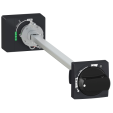
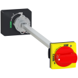
GV4 with Rotary Handle: GV4L, GV4P, or GV4LE, GV4PE, GV4PEM with GV4ADN01, GV4ADN02 Direct Mounting Rotary Handle
Dimensions

GV4L, GV4P, GV4LE, GV4PE, GV4PEM
Panel Mounting with M4 Screws

Door Cut-Out for Rotary Handle

Minimum Safety Clearance

Toggle-type, rotary handle-type: identical clearance values.
Safety Clearance (mm) | ||||||
|---|---|---|---|---|---|---|
Painted Sheet Metal | Bare Sheet Metal | |||||
A | B | C | A | B | C | |
No accessory | 30 | 0 | 0 | 40 | 0 | 5 |
Interphase barriers | 0 | 0 | 0 | 0 | 0 | 5 |
Long terminal shield | 0 | 0 | 0 | 0 | 0 | 5 |
Magnetic Motor Circuit Breakers
GV4P, GV4PE, GV4PEM

Items usually bought together

Need more information? Check our technical FAQs!
Easily find answers to the most frequently asked questions.