
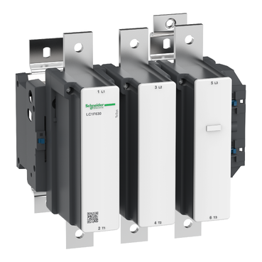

LC1F630M7
Recommended replacement(s)


| Range | TeSys |
|---|---|
| Range of product | TeSys F |
| Product or component type | Contactor |
| Device short name | LC1F |
| Contactor application | Resistive load Motor control |
| Utilisation category | AC-3 AC-1 AC-4 |
| Poles description | 3P |
| [Ue] rated operational voltage | <= 1000 V AC 50/60 Hz <= 460 V DC |
| [Uc] control circuit voltage | 220 V AC 40...400 Hz |
| [Ie] rated operational current | 1000 A (at <40 °C) at <= 440 V AC AC-1 630 A (at <55 °C) at <= 440 V AC AC-3 |
| [Uimp] rated impulse withstand voltage | 8 kV |
|---|---|
| [Ith] conventional free air thermal current | 1000 A (at 40 °C) 1250 A |
| Rated breaking capacity | 5040 A conforming to IEC 60947-4-1 |
| [Icw] rated short-time withstand current | 5050 A 40 °C - 10 s 4400 A 40 °C - 30 s 3400 A 40 °C - 1 min 2200 A 40 °C - 3 min 1600 A 40 °C - 10 min |
| Associated fuse rating | 1000 A gG at <= 440 V 630 A aM at <= 440 V |
| Average impedance | 0.12 mOhm - Ith 1000 A 50 Hz |
| [Ui] rated insulation voltage | 1000 V conforming to IEC 60947-4-1 1500 V conforming to VDE 0110 group C |
| Power dissipation per pole | 120 W AC-1 48 W AC-3 |
| Overvoltage category | III |
| power pole contact composition | 3 NO |
| Motor power kW | 335 kW at 380...400 V AC 50/60 Hz (AC-3) 375 kW at 415 V AC 50/60 Hz (AC-3) 400 kW at 440 V AC 50/60 Hz (AC-3) 400 kW at 500 V AC 50/60 Hz (AC-3) 450 kW at 660...690 V AC 50/60 Hz (AC-3) 450 kW at 1000 V AC 50/60 Hz (AC-3) 200 kW at 220...230 V AC 50/60 Hz (AC-3) 100 kW at 400 V AC 50/60 Hz (AC-4) |
| Control circuit voltage limits | Operational: 0.85...1.1 Uc 40...400 Hz (at 55 °C) Drop-out: 0.25...0.5 Uc 40...400 Hz (at 55 °C) |
| Mechanical durability | 5 Mcycles |
| Inrush power in VA | 1650 VA, 40...400 Hz cos phi 0.9 (at 20 °C) |
| Hold-in power consumption in VA | 22 VA, 40...400 Hz cos phi 0.9 (at 20 °C) |
| Maximum operating rate | 1200 cyc/h 55 °C |
| Operating time | 40...80 ms closing 100...200 ms opening |
| Connections - terminals | Control circuit: screw clamp terminals 1 cable(s) 1…4 mm²flexible without cable end Control circuit: screw clamp terminals 2 cable(s) 1…4 mm²flexible without cable end Control circuit: screw clamp terminals 1 cable(s) 1…4 mm²flexible with cable end Control circuit: screw clamp terminals 2 cable(s) 1…2.5 mm²flexible with cable end Control circuit: screw clamp terminals 1 cable(s) 1…4 mm²solid without cable end Control circuit: screw clamp terminals 2 cable(s) 1…4 mm²solid without cable end Power circuit: bar 2 cable(s) - busbar cross section: 60 x 5 mm Power circuit: bolted connection |
| Tightening torque | Control circuit: 1.2 N.m Power circuit: 58 N.m |
| Mounting support | Plate |
| Heat dissipation | 20 W |
| motor power range | 250…500 kW at 380…440 V 3 phases 110…220 kW at 200…240 V 3 phases 250…500 kW at 480…500 V 3 phases |
| Motor starter type | Direct on-line contactor |
| Contactor coil voltage | 220 V AC standard |
| Standards | EN 60947-1 IEC 60947-4-1 JIS C8201-4-1 IEC 60947-1 EN 60947-4-1 |
| Product certifications | LROS (Lloyds register of shipping) CB UL RMRoS CSA ABS BV DNV RINA UKCA |
| Compatibility code | LC1F |
| Control circuit type | AC at 40...400 Hz |
| IP degree of protection | IP20 front face with shrouds conforming to IEC 60529 IP20 front face with shrouds conforming to VDE 0106 |
|---|---|
| Protective treatment | TH |
| Ambient air temperature for operation | -5…55 °C |
| Ambient air temperature for storage | -60…80 °C |
| Permissible ambient air temperature around the device | -40…70 °C |
| Height | 304 mm |
| Width | 309 mm |
| Depth | 255 mm |
| Operating altitude | 3000 m without derating |
| Net weight | 18.6 kg |
| Unit Type of Package 1 | PCE |
|---|---|
| Number of Units in Package 1 | 1 |
| Package 1 Height | 30.000 cm |
| Package 1 Width | 37.000 cm |
| Package 1 Length | 47.000 cm |
| Package 1 Weight | 18.433 kg |
| Unit Type of Package 2 | P06 |
| Number of Units in Package 2 | 4 |
| Package 2 Height | 75.000 cm |
| Package 2 Width | 60.000 cm |
| Package 2 Length | 80.000 cm |
| Package 2 Weight | 82.232 kg |
| Warranty | 12 months |
|---|


NOTE: X1 (mm) = Minimum electrical clearance according to operating voltage and breaking capacity.
LC1 | a | G supplied | G min. | G max. | J1 | Q | Q1 | |
|---|---|---|---|---|---|---|---|---|
F630 | 2P | 309 | 180 | 100 | 195 | 68.5 | 102 | 127 |
F630, F800 | 3P | 309 | 180 | 100 | 195 | 68.5 | 60 | 89 |
F630 | 4P | 389 | 240 | 150 | 275 | 88.5 | 60 | 89 |
Voltage | 200…500 V | 690…1000 V | 200…690 V | 1000 V |
|---|---|---|---|---|
LC1 F630 | 20 | 30 | – | – |
LC1 F800 | – | – | 10 | 20 |
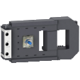
NOTE: For customer assembly, with mechanical interlock (MI) LA9 F, fixing recommended on AM1 EC uprights (please consult your Regional Sales Office). 2 x LC1 identical or different ratings (LC1 F115 to F630 and F800).
Assembly A

Assembly A(7) - Mechanical interlock reference
G3 3P | G3 4P | H min. | H max. | H1 min. | H1 max. | J1 3P | J1 4P | |
|---|---|---|---|---|---|---|---|---|
LA9 FF4F | 0 | 0 | 200 | 310 | 80 | 190 | 137 | 155.5 |
LA9 FG4F | 3 | 4 | 210 | 300 | 90 | 180 | 139.5 | 159.5 |
LA9 FG4G | 0 | 0 | 220 | 310 | 100 | 190 | 139.5 | 159.5 |
J2 3P | J2 4P | J3 3P | J3 4P | J4 3P | J4 4P | |
|---|---|---|---|---|---|---|
LA9 FF4F | 137 | 155.5 | 48.5 | 67 | 48.5 | 67 |
LA9 FG4F | 137 | 155.5 | 53 | 73 | 54 | 69 |
LA9 FG4G | 139.5 | 159.5 | 53 | 73 | 53 | 73 |
Assembly B

Assembly B(7) - Mechanical interlock reference
G1 3P | G1 4P | G3 3P | G3 4P | G5 3P | G5 4P | H min. | H max. | |
|---|---|---|---|---|---|---|---|---|
LA9 FH4F | 96 | 96 | 21 | 27 | 60 | 83 | 240 | 380 |
LA9 FJ4F | 80 | 80 | 45 | 26 | 83 | 83 | 250 | 380 |
LA9 FK4F | 80 | 140 | 45 | 26 | 83 | 83 | 270 | 380 |
LA9 FL4F | 180 | 240 | 35 | 17 | 74 | 74 | 310 | 380 |
LA9 FH4G | 96 | 96 | 19 | 23 | 60 | 83 | 250 | 380 |
LA9 FJ4G | 80 | 80 | 42 | 22 | 83 | 83 | 250 | 380 |
LA9 FK4G | 80 | 140 | 42 | 22 | 83 | 83 | 270 | 380 |
LA9 FL4G | 180 | 240 | 33 | 13 | 74 | 74 | 310 | 380 |
H1 min. | H1 max. | J1 3P | J1 4P | J2 3P | J2 4P | J4 3P | J4 4P | |
|---|---|---|---|---|---|---|---|---|
LA9 FH4F | 110 | 250 | 157.5 | 181.5 | 137 | 155.5 | 48.5 | 67 |
LA9 FJ4F | 80 | 210 | 144.5 | 192.5 | 137 | 155.5 | 48.5 | 67 |
LA9 FK4F | 100 | 210 | 164.5 | 219.5 | 137 | 155.5 | 48.5 | 67 |
LA9 FL4F | 140 | 210 | 248.5 | 328.5 | 137 | 155.5 | 48.5 | 67 |
LA9 FH4G | 120 | 250 | 157.5 | 181.5 | 139.5 | 159.5 | 53 | 73 |
LA9 FJ4G | 90 | 220 | 144.5 | 192.5 | 139.5 | 159.5 | 53 | 73 |
LA9 FK4G | 110 | 220 | 164.5 | 219.5 | 139.5 | 159.5 | 53 | 73 |
LA9 FL4G | 150 | 220 | 248.5 | 328.5 | 139.5 | 159.5 | 53 | 73 |
Assembly C


Assembly C(7)
G1 3P | G1 4P | G2 3P | G2 4P | G3 3P | G3 4P | G4 3P | G4 4P | G5 3P | G5 4P | |
|---|---|---|---|---|---|---|---|---|---|---|
LA9 FH4H | 96 | 96 | 96 | 96 | 0 | 0 | 60 | 83 | 60 | 83 |
LA9 FJ4H | 80 | 80 | 96 | 96 | 23 | 0 | 60 | 83 | 83 | 83 |
LA9 FK4H | 80 | 140 | 96 | 96 | 23 | 0 | 60 | 83 | 83 | 83 |
LA9 FL4H | 180 | 240 | 96 | 96 | 14 | 9(8) | 60 | 83 | 74 | 74 |
LA9 FJ4J | 80 | 80 | 80 | 80 | 0 | 0 | 83 | 83 | 83 | 83 |
LA9 FK4J | 80 | 140 | 80 | 80 | 0 | 0 | 83 | 83 | 83 | 83 |
LA9 FL4J | 180 | 240 | 80 | 80 | 9(8) | 9(8) | 83 | 83 | 74 | 74 |
LA9 FK4K | 80 | 140 | 80 | 140 | 0 | 0 | 83 | 83 | 83 | 83 |
LA9 FL4K | 180 | 240 | 80 | 140 | 9(8) | 9(8) | 83 | 83 | 74 | 74 |
LA9 FL4L | 180 | 240 | 180 | 240 | 0 | 0 | 74 | 74 | 74 | 74 |
H min. | H max. | H1 min. | H1 max. | J1 3P | J1 4P | J2 3P | J2 4P | |
|---|---|---|---|---|---|---|---|---|
LA9 FH4H | 250 | 380 | 130 | 260 | 157.5 | 181.5 | 157.5 | 181.5 |
LA9 FJ4H | 260 | 380 | 110 | 230 | 144.5 | 192.5 | 157.5 | 181.5 |
LA9 FK4H | 280 | 380 | 130 | 230 | 164.5 | 219.5 | 157.5 | 181.5 |
LA9 FL4H | 330 | 380 | 170 | 220 | 248.5 | 328.5 | 157.5 | 181.5 |
LA9 FJ4J | 260 | 380 | 60 | 200 | 144.5 | 192.5 | 144.5 | 192.5 |
LA9 FK4J | 280 | 380 | 100 | 200 | 164.5 | 219.5 | 144.5 | 192.5 |
LA9 FL4J | 325 | 380 | 140 | 195 | 248.5 | 329.5 | 144.5 | 192.5 |
LA9 FK4K | 300 | 380 | 120 | 200 | 164.5 | 329.5 | 164.5 | 219.5 |
LA9 FL4K | 345 | 380 | 160 | 195 | 248.5 | 328.5 | 164.5 | 219.5 |
LA9 FL4L | 380 | 380 | 200 | 200 | 248.5 | 328.5 | 248.5 | 328.5 |

LC1 F115 to F630, F1250(coil LX1 F  )
)

LC1 F115 to F630 , F1250 (coil LX4 F  )
)
LC1 F115 to F265 (coil LX9 F )
LC1 F800 (coil LX8 F / )
Need more information? Check our technical FAQs!
Easily find answers to the most frequently asked questions.
LC1F630M7 is replaced by: