
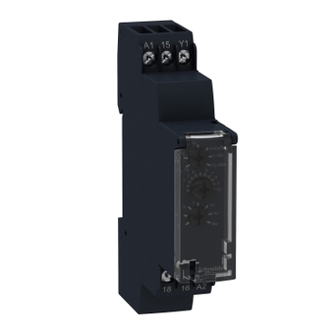


RE17RMMU
| Range of product | Harmony Timer Relays |
|---|---|
| Discrete output type | Relay |
| Product or component type | Modular timing relay |
| Width | 17.5 mm |
| Device short name | RE17R |
| Time delay type | Power on-delay On-delay and off-delay Interval Off-delay Symmetrical flashing |
| Time delay range | 6...60 min 1...10 h 0.1...1 s 1...10 s 1...10 min 10...100 h 6...60 s |
| Nominal output current | 8 A |
| Contacts type and composition | 1 C/O |
|---|---|
| Contacts material | Cadmium free |
| Height | 90 mm |
| Depth | 72 mm |
| Control type | Selector switch front panel |
| [Us] rated supply voltage | 24...240 V AC 50/60 Hz 24 V DC |
| Voltage range | 0.85...1.1 Us |
| Supply frequency | 50...60 Hz +/- 5 % |
| release of input voltage | 10 V |
| Connections - terminals | Screw terminals, 1 x 0.5...1 x 3.3 mm² (AWG 20...AWG 12) solid without cable end Screw terminals, 2 x 0.5...2 x 2.5 mm² (AWG 20...AWG 14) solid without cable end Screw terminals, 1 x 0.2...1 x 2.5 mm² (AWG 24...AWG 14) flexible with cable end Screw terminals, 2 x 0.2...2 x 1.5 mm² (AWG 24...AWG 16) flexible with cable end |
| Tightening torque | 0.6…1 N.m conforming to IEC 60947-1 |
| Housing material | Self-extinguishing |
| Repeat accuracy | +/- 0.5 % conforming to IEC 61812-1 |
| Temperature drift | +/- 0.05 %/°C |
| Voltage drift | +/- 0.2 %/V |
| Setting accuracy of time delay | +/- 10 % of full scale at 25 °C conforming to IEC 61812-1 |
| Time delay type | Power on-delay - A- Power on-delay relay On-delay and off-delay - Ac- On-delay and off-delay relay w/ control signal Power on-delay - At- Power on-delay relay w/ pause/summation (Y1) Interval - B- Single interval relay w/ control signal Interval - Bw- Double interval relay w/ control signal Off-delay - C- Off-delay relay w/ control signal Symmetrical flashing - D- Symmetrical flashing relay (starting pulse-off) Symmetrical flashing - Di- Symmetrical flashing relay (starting pulse-on) Interval - H- Interval relay Interval - Ht- Interval relay w/ pause/summation (Y1) |
| control signal pulse width | 100 ms with load in parallel typical 30 ms typical |
| Insulation resistance | 100 MOhm at 500 V DC conforming to IEC 60664-1 |
| Reset time | 120 ms on de-energisation typical |
| On-load factor | 100 % |
| Power consumption in VA | 0…32 VA at 240 V AC |
| Maximum power consumption in W | 0.6 W at 24 V DC |
| Minimum switching current | 10 mA at 5 V DC |
| Maximum switching current | 8 A AC/DC |
| Maximum switching voltage | 250 V AC |
| breaking capacity | 2000 VA |
| operating frequency | 10 Hz |
| Electrical durability | 100000 cycles (8 A at 250 V AC maximum) for resistive load |
| Mechanical durability | 10000000 cycles |
| Dielectric strength | 2.5 kV 1 mA/1 minute 50 Hz conforming to IEC 61812-1 |
| [Uimp] rated impulse withstand voltage | 5 kV during 1.2/50 µs |
| power on delay | 100 ms |
| Marking | CE |
| Creepage distance | 4 kV/3 conforming to IEC 60664-1 |
| Safety reliability data | B10d = 270000 MTTFd = 296.8 years |
| Mounting position | Any position in relation to normal vertical mounting plane |
| Mounting support | 35 mm DIN rail conforming to IEC 60715 |
| Local signalling | LED indicator for on steady: relay energised, no timing in progress LED indicator for flashing: timing in progress 80 % ON and 20 % OFF LED indicator for pulsing: relay de-energised, no timing in progress (except function Di-D, Li-L) 5 % ON and 95 % OFF |
| Function available | A- Power on-delay relay-1 C/O Ac- On-delay and off-delay relay w/ control signal-1 C/O At- Power on-delay relay w/ pause/summation (Y1)-1 C/O B- Single interval relay w/ control signal-1 C/O Bw- Double interval relay w/ control signal-1 C/O C- Off-delay relay w/ control signal-1 C/O D- Symmetrical flashing relay (starting pulse-off)-1 C/O Di- Symmetrical flashing relay (starting pulse-on)-1 C/O H- Interval relay-1 C/O Ht- Interval relay w/ pause/summation (Y1)-1 C/O |
| Net weight | 0.07 kg |
| Control type | Without test button |
| Number of functions | 10 |
| Time delay type | A, Ac, At, B, Bw, C, D, Di, H, Ht |
| Functionality | Multifunction |
| Compatibility code | RE17 |
| Immunity to microbreaks | 20 ms |
|---|---|
| Standards | 2006/95/EC 2004/108/EC IEC 61812-1 IEC 61000-6-2 IEC 61000-6-3 IEC 61000-6-4 IEC 61000-6-1 |
| Product certifications | CSA GL cULus |
| Ambient air temperature for storage | -30…60 °C |
| Ambient air temperature for operation | -20…60 °C |
| IP degree of protection | IP20 (terminal block) conforming to IEC 60529 IP40 (housing) conforming to IEC 60529 IP50 (front panel) conforming to IEC 60529 |
| Vibration resistance | 20 m/s² (f= 10…150 Hz) conforming to IEC 60068-2-6 |
| Shock resistance | 15 gn for 11 ms conforming to IEC 60068-2-27 |
| Relative humidity | 93 % without condensation conforming to IEC 60068-2-30 |
| Electromagnetic compatibility | Electrostatic discharge immunity test: (in contact), level 3, 6 kV, conforming to IEC 61000-4-2 Electrostatic discharge immunity test: (in air), level 3, 8 kV, conforming to IEC 61000-4-2 Susceptibility to electromagnetic fields: (80 MHz to 1 GHz), level 3, 10 V/m, conforming to IEC 61000-4-3 Electrical fast transient/burst immunity test: (capacitive connecting clip), level 3, 1 kV, conforming to IEC 61000-4-4 Electrical fast transient/burst immunity test: (direct), level 3, 2 kV, conforming to IEC 61000-4-4 1.2/50 µs shock waves immunity test: (differential mode), level 3, 1 kV, conforming to IEC 61000-4-5 1.2/50 µs shock waves immunity test: (common mode), level 3, 2 kV, conforming to IEC 61000-4-5 Conducted RF disturbances: (0.15...80 MHz), level 3, 10 V, conforming to IEC 61000-4-6 Voltage dips and interruptions immunity test: (1 cycle), 0 %, conforming to IEC 61000-4-11 Voltage dips and interruptions immunity test: (25/30 cycles), 70 %, conforming to IEC 61000-4-11 Conducted and radiated emissions: , class B, conforming to EN 55022 |
| Unit Type of Package 1 | PCE |
|---|---|
| Number of Units in Package 1 | 1 |
| Package 1 Height | 2.600 cm |
| Package 1 Width | 7.800 cm |
| Package 1 Length | 9.500 cm |
| Package 1 Weight | 80.000 g |
| Unit Type of Package 2 | S02 |
| Number of Units in Package 2 | 40 |
| Package 2 Height | 15.000 cm |
| Package 2 Width | 30.000 cm |
| Package 2 Length | 40.000 cm |
| Package 2 Weight | 3.690 kg |
| Unit Type of Package 3 | P06 |
| Number of Units in Package 3 | 640 |
| Package 3 Height | 75.000 cm |
| Package 3 Width | 60.000 cm |
| Package 3 Length | 80.000 cm |
| Package 3 Weight | 65.700 kg |


1) Contact Y1:
Control for functions B, C, Ac, Bw, Ad, Ah, N, O, W, T, Tt.
Partial stop for functions At, Ht and Pt.
Function D if Di selected.
Not used for functions A, H and P.
The timing period T begins on energisation. After timing, the output(s) R close(s). The second output can be either timed or instantaneous.


2 timed outputs (R1/R2) or 1 timed output (R1) and 1 instantaneous output (R2 inst.)
After energisation of power supply and energization of Y1 causes the timing period T to start.
At the end of this timing period, the output(s) R close(s).
When deenergization of Y1, the timing T starts.
At the end of this timing period T,the output(s) R revert(s) to its/their initial position.
The second output (R2) can be either timed (when set to "TIMED") or instantaneous (when set to "INST").


After power-up, the first opening of control contact C starts the timing. Timing can be interrupted each time control contact closes. When the cumulative total of time periods elapsed reaches the pre-set value T, the output relay closes.

T = t1 + t2 +...
After power-up, pulsing or maintaining control contact C starts the timing T. The output R closes for the duration of the timing period T then reverts to its initial state.

On closing and opening of control contact C, the output R closes for the duration of the timing period T.

After power-up and closing of the control contact C, the output R closes. When control contact C re-opens, timing T starts. At the end of the timing period, the output(s) R revert(s) to its/their initial state. The second output can be either timed or instantaneous.


2 timed outputs (R1/R2) or 1 timed output (R1) and 1 instantaneous output (R2 inst.)
On energisation of power supply, output(s) R starts at its/their initial state for timing duration T then change(s) to output(s) R close(s) for the same timing duration T.This cycle is repeated indefintely until power supply removal.Specially for RE17*, RE22R2AMU, RE22R2MMW, RE22R2MMU, RE22R2MJU,this D function can only be initiated by energizing Y1 permanently.The second output (R2) can be either timed (when set to "TIMED") or instantaneous (when set to "INST").


Repetitive cycle with two timing periods T of equal duration, with output(s) R changing state at the end of each timing period T.
The second output can be either timed or instantaneous.


2 timed outputs (R1/R2) or 1 timed output (R1) and 1 instantaneous output (R2 inst.)
On energisation of the relay, timing period T starts and the output(s) R close(s). At the end of the timing period T, the output(s) R revert(s) to its/their initial state. The second output can be either timed or instantaneous.


2 timed outputs (R1/R2) or 1 timed output (R1) and 1 instantaneous output (R2 inst.)
On energisation of power supply, output(s) R close(s) and timing period T starts.
The timing can be interrupted / paused each time X1 energizes.
When the cumulative total of time periods elapsed reaches the pre-set value T, the output(s) R revert(s) to its/their initial state Reenergization of X1 will also cause output(s) R close(s) if the time has elapsed and restart the same operation as described at the beginning.
Except for RE17*, RE22R2MMW, RENF22R2MMW, RE22R2MMU and RE22R2MJU, timing can be interrupted / paused each time Y1 energizes.
The second output (R2) can be either timed (when set to “TIMED” or instantaneous (when set to “INST”).

T = t1 + t2 +...

T = t1 + t2 +...

T = t1 + t2 +...

T = t1 + t2 +...
 Relay de-energised
 Relay energised
 Output open
 Output closed
C | Control contact |
G | Gate |
R | Relay or solid state output |
R1/R2 | 2 timed outputs |
R2 inst. | The second output is instantaneous if the right position is selected |
T | Timing period |
Ta - | Adjustable On-delay |
Tr - | Adjustable Off-delay |
U | Supply |
Items usually bought together

Need more information? Check our technical FAQs!
Easily find answers to the most frequently asked questions.