
Roll over image to zoom in


+ 5
2 videos
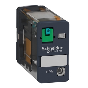
RPM12BD
Contacts type and composition:
Control type:
status LED:
[Uc] control circuit voltage:
Environmental Data
Total lifecycle Carbon footprint
14
Use Better
Packaging made with recycled cardboard
Yes
Use Again
Take-back
No
This Harmony RPM power plug-in relay has a coil control voltage of 24V DC and has 1 changeover contact SPDT (single pole double throw) with a rating of 15A. It has large choice of number of contacts for high rated current use. It also offers LED indicator to alert on the current status of the relay. It helps to reduce the size of enclosures and increase machine reliability, you can mount nearly everywhere. This RPM product is IP40. Workability for hard-wired logic automated systems to complement the functions of industrial programmable logic controllers (PLCs). Status display with LED, clearly signal both in the day and night.


| Range of product | Harmony Electromechanical Relays |
|---|---|
| Series name | RPM series |
| Product or component type | Plug-in relay |
| Contacts type and composition | 1 C/O |
| Relay type | Power relay |
| status LED | With |
| [Uc] control circuit voltage | 24 V DC |
| Minimum switching capacity | 170 mW at 10 mA, 17 V |
| Release time | 20 ms at nominal voltage |
| Ambient air temperature for operation | -40…55 °C |
| [Ithe] conventional enclosed thermal current | 15 A at -40…55 °C |
| Control type | Lockable test button |
|---|---|
| [Ie] rated operational current | 15 A at 277 V (AC) conforming to UL 15 A at 28 V (DC) conforming to UL 15 A at 250 V (AC) NO conforming to IEC 15 A at 28 V (DC) NO conforming to IEC 7.5 A at 250 V (AC) NC conforming to IEC 7.5 A at 28 V (DC) NC conforming to IEC |
| Degree of protection (Housing only) | IP40 conforming to IEC 60529 |
| Rated operational voltage limits | 19.2...26.4 V DC |
| [Ui] rated insulation voltage | 250 V conforming to IEC 300 V conforming to CSA 300 V conforming to UL |
| Maximum switching voltage | 250 V conforming to IEC |
| Drop-out voltage threshold | >= 0.1 Uc DC |
| Maximum switching capacity | 3750 VA 420 W |
| Mechanical durability | 10000000 cycles |
| Electrical durability | 100000 cycles for resistive load |
| Safety reliability data | B10d = 100000 |
| Operating rate | <= 1200 cycles/hour under load <= 18000 cycles/hour no-load |
| Utilisation coefficient | 20 % |
| Dielectric strength | 1500 V AC between contacts with micro disconnection 2000 V AC between coil and contact with reinforced |
| [Uimp] rated impulse withstand voltage | 4 kV during 1.2/50 µs |
| Protection category | RT I |
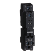
| Mounting support | Plug-in |
| Operating position | Any position |
| Test levels | Level A group mounting |
| Device presentation | Complete product |
| Contacts material | AgNi |
| Shape of pin | Flat (faston type) |
| Net weight | 0.026 kg |
| Pollution degree | 3 |
|---|---|
| Standards | IEC 61810-1 UL 508 CSA C22.2 No 14 |
| Product certifications | CSA EAC UL |
| Ambient air temperature for storage | -40…85 °C |
| Vibration resistance | 3 gn, amplitude = +/- 1 mm (f = 10…150 Hz)5 cycles in operation 5 gn, amplitude = +/- 1 mm (f = 10…150 Hz)5 cycles not operating |
| Shock resistance | 15 gn for in operation 30 gn for not operating |
| Unit Type of Package 1 | PCE |
|---|---|
| Number of Units in Package 1 | 1 |
| Package 1 Height | 1.400 cm |
| Package 1 Width | 2.600 cm |
| Package 1 Length | 3.900 cm |
| Package 1 Weight | 24.000 g |
| Unit Type of Package 2 | BB1 |
| Number of Units in Package 2 | 10 |
| Package 2 Height | 3.300 cm |
| Package 2 Width | 8.300 cm |
| Package 2 Length | 11.000 cm |
| Package 2 Weight | 274.000 g |
| Unit Type of Package 3 | S02 |
| Number of Units in Package 3 | 360 |
| Package 3 Height | 15.000 cm |
| Package 3 Width | 30.000 cm |
| Package 3 Length | 40.000 cm |
| Package 3 Weight | 10.382 kg |
| Warranty | 12 months |
|---|
Schneider Electric aims to achieve Net Zero status by 2050 through supply chain partnerships, lower impact materials, and circularity via our ongoing “Use Better, Use Longer, Use Again” campaign to extend product lifetimes and recyclability.
Total lifecycle Carbon footprint
14
Environmental Disclosure
Use Better
Packaging made with recycled cardboard
Yes
Packaging without single use plastic
Yes
Pro-active compliance (Product out of EU RoHS legal scope)
REACh Regulation
Use Again
End of life manual availability
No need of specific recycling operations
Take-back
No
Dimensions
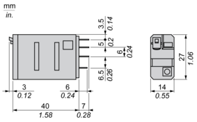
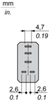
Pin Side View
Wiring Diagram
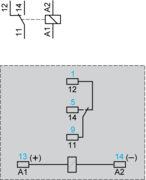
Symbols shown in blue correspond to Nema marking.
Electrical Durability of Contacts
Durability (inductive load) = durability (resistive load) x reduction coefficient.
Resistive AC load
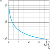
X Switching capacity (kVA)
Y Durability (Number of operating cycles)
Reduction coefficient for inductive AC load (depending on power factor cos ϕ)
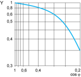
Y Reduction coefficient (A)
Maximum switching capacity on resistive DC load
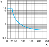
X Voltage DC
Y Current DC
Note : These are typical curves, actual durability depends on load, environment, duty cycle, etc.
Need more information? Check our technical FAQs!
Easily find answers to the most frequently asked questions.