
Roll over image to zoom in


+ 4
2 videos
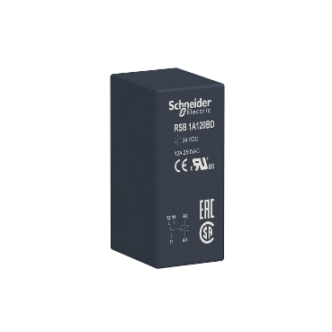
RSB1A120BD
Environmental Data
Total lifecycle Carbon footprint
5
Use Better
Packaging made with recycled cardboard
Yes
Use Again
Take-back
No
This Harmony RSB interfacing plug-in relay has a control coil voltage of 24V DC and has 1 changeover contact single pole double throw with a rating of 12A. It helps to reduce the size of enclosures and increases machine reliability, you can mount nearly everywhere. Plug in type allows easy installation and maintenance. The product is IP40 and has a transparent cover allowing operator to visually inspect the status of contacts.
| Range of product | Harmony Electromechanical Relays |
|---|---|
| Series name | RSB series |
| Product or component type | Plug-in relay |
| Relay type | Interface relay |
| Contacts type and composition | 1 C/O |
| status LED | Without |
| [Uc] control circuit voltage | 24 V DC |
| Control type | Without lockable test button |
| [Ithe] conventional enclosed thermal current | 12 A at -40…40 °C |
| Average resistance | 1440 Ohm network: AC at 20 °C +/- 10 % |
|---|---|
| [Ue] rated operational voltage | 16.8...36 V DC |
| [Uimp] rated impulse withstand voltage | 3.6 kV conforming to IEC 61000-4-5 |
| [Ie] rated operational current | 12 A (AC-1/DC-1) NO conforming to IEC 6 A (AC-1/DC-1) NC conforming to IEC |
| [Ui] rated insulation voltage | 400 V conforming to IEC 60947 |
| Maximum switching voltage | 300 V DC conforming to IEC |
| Drop-out voltage threshold | >= 0.1 Uc DC |
| Load current | 12 A at 250 V AC 12 A at 28 V DC |
| minimum switching current | 10 mA |
| Maximum switching capacity | 3000 VA/336 W |
| minimum switching voltage | 12 V |
| Minimum switching capacity | 120 mW at 10 mA, 12 V |
| Operating time | 20 ms operating 20 ms reset |
| Mechanical durability | 30000000 cycles |
| Electrical durability | 100000 cycles, 12 A at 250 V, AC-1 NO 100000 cycles, 6 A at 250 V, AC-1 NC |
| Safety reliability data | B10d = 100000 |
| Operating rate | <= 600 cycles/hour under load <= 18000 cycles/hour no-load |
| Average coil consumption | 0.45 W DC |
| Removable legend | Without |
| Protection category | RT I |
| Operating position | Any position |
| Test levels | Level A group mounting |
| Device presentation | Complete product |
| Sale per indivisible quantity | 10 |
| Contacts material | Silver alloy (AgNi) |
| Shape of pin | Flat (PCB type) |
| Net weight | 0.014 kg |
| Compatibility code | RSB |
| Dielectric strength | 1000 V AC between contacts 2500 V AC between poles 5000 V AC between coil and contact |
|---|---|
| Vibration resistance | +/- 1 mm (f= 10…55 Hz) conforming to IEC 60068-2-6 |
| IP degree of protection | IP40 conforming to IEC 60529 |
| Ambient air temperature for operation | -40…85 °C (DC) |
| Standards | CSA C22.2 No 14 UL 508 IEC 61810-1 |
| Product certifications | UL CSA EAC |
| Ambient air temperature for storage | -40…85 °C |
| Shock resistance | 10 gn (duration = 11 ms) for not operating conforming to IEC 60068-2-27 5 gn (duration = 11 ms) for in operation conforming to IEC 60068-2-27 |
| Unit Type of Package 1 | PCE |
|---|---|
| Number of Units in Package 1 | 1 |
| Package 1 Height | 1.800 cm |
| Package 1 Width | 2.000 cm |
| Package 1 Length | 2.900 cm |
| Package 1 Weight | 13.000 g |
| Unit Type of Package 2 | BB1 |
| Number of Units in Package 2 | 10 |
| Package 2 Height | 1.700 cm |
| Package 2 Width | 2.800 cm |
| Package 2 Length | 33.000 cm |
| Package 2 Weight | 142.000 g |
| Unit Type of Package 3 | S01 |
| Number of Units in Package 3 | 350 |
| Package 3 Height | 15.000 cm |
| Package 3 Width | 15.000 cm |
| Package 3 Length | 40.000 cm |
| Package 3 Weight | 5.175 kg |
| Warranty | 12 months |
|---|
Schneider Electric aims to achieve Net Zero status by 2050 through supply chain partnerships, lower impact materials, and circularity via our ongoing “Use Better, Use Longer, Use Again” campaign to extend product lifetimes and recyclability.
Total lifecycle Carbon footprint
5
Environmental Disclosure
Use Better
Packaging made with recycled cardboard
Yes
Packaging without single use plastic
No
Pro-active compliance (Product out of EU RoHS legal scope)
SCIP Number
45b41055-6c52-408d-9c0c-5c663b810f29
REACh Regulation
Use Again
End of life manual availability
No need of specific recycling operations
Take-back
No
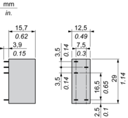
Dimensions
Wiring Diagram
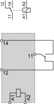
NOTE: For DC input, A1 have to be +, otherwise it would short circuit from protection module
Electrical Durability of Contacts
Durability (inductive load) = durability (resistive load) x reduction coefficient.
Resistive AC load

X Switching capacity (kVA)
Y Durability (Number of operating cycles)
Reduction coefficient for inductive AC load (depending on power factor cos ϕ)

Y Reduction coefficient (A)
Maximum switching capacity on resistive DC load

X Voltage DC
Y Current DC
Note : These are typical curves, actual durability depends on load, environment, duty cycle, etc.
Need more information? Check our technical FAQs!
Easily find answers to the most frequently asked questions.