
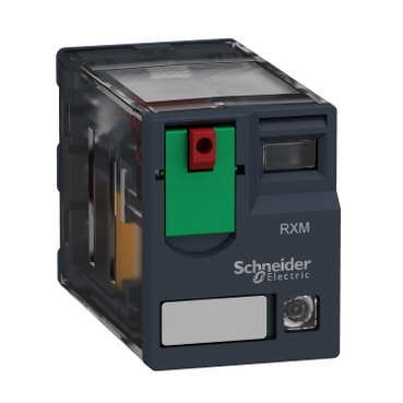


RXM2AB2P7
status LED:
[Uc] control circuit voltage:


| Range of product | Harmony Electromechanical Relays |
|---|---|
| Series name | RXM series |
| Product or component type | Plug-in relay |
| Relay type | Miniature relay |
| Contacts type and composition | 2 C/O |
| status LED | With |
| Control type | Lockable test button |
| [Uc] control circuit voltage | 230 V AC 50/60 Hz |
| [Ithe] conventional enclosed thermal current | 12 A |
| Continuous output current | 10 A |
| [Uimp] rated impulse withstand voltage | 4 kV during 1.2/50 µs |
|---|---|
| [Ie] rated operational current | 12 A at 28 V (DC) NO conforming to IEC 12 A at 250 V (AC) NO conforming to IEC 6 A at 28 V (DC) NC conforming to IEC 6 A at 250 V (AC) NC conforming to IEC 12 A at 28 V (DC) conforming to UL 12 A at 277 V (AC) conforming to UL |
| Minimum switching capacity | 170 mW at 10 mA, 17 V |
| Electrical durability | 100000 cycles for resistive load |
| Average coil consumption in VA | 1.2 at 60 Hz |
| Rated operational voltage limits | 184...253 V AC |
| [Ui] rated insulation voltage | 250 V conforming to IEC 300 V conforming to CSA 300 V conforming to UL |
| Average consumption | 1.2 VA at 60 Hz |
| Maximum switching voltage | 250 V conforming to IEC |
| Drop-out voltage threshold | >= 0.15 Uc |
| Load current | 12 A at 250 V AC 12 A at 28 V DC |
| Operating time | 20 ms |
| Maximum switching capacity | 3000 VA/336 W |
| Average resistance | 15000 Ohm at 20 °C +/- 15 % |
| Mechanical durability | 10000000 cycles |
| Safety reliability data | B10d = 100000 |
| Operating rate | <= 1200 cycles/hour under load <= 18000 cycles/hour no-load |
| Utilisation coefficient | 20 % |
| CAD overall height | 82.8 mm |
| CAD overall depth | 80.35 mm |
| reset time | 20 ms |
| Dielectric strength | 1300 V AC between contacts with micro disconnection 2000 V AC between coil and contact with basic insulation 2000 V AC between poles with basic insulation |
| Compatibility code | RXM |
| Protection category | RT I |
| Pollution degree | 3 |
| Operating position | Any position |
| Test levels | Level A group mounting |
| Device presentation | Complete product |
| Contacts material | AgNi |
| Shape of pin | Flat (faston type) |
| Net weight | 0.037 kg |
| Ambient air temperature for operation | -40…55 °C |
|---|---|
| IP degree of protection | IP40 conforming to IEC 60529 |
| Standards | IEC 61810-1 UL 508 CSA C22.2 No 14 |
| Product certifications | UL Lloyd's CE CSA GOST IECEE CB Scheme |
| Ambient air temperature for storage | -40…85 °C |
| Vibration resistance | 3 gn, amplitude = +/- 1 mm (f = 10…150 Hz)5 cycles in operation 5 gn, amplitude = +/- 1 mm (f = 10…150 Hz)5 cycles not operating |
| Shock resistance | 10 gn for in operation 30 gn for not operating |
| Unit Type of Package 1 | PCE |
|---|---|
| Number of Units in Package 1 | 1 |
| Package 1 Height | 2.6 cm |
| Package 1 Width | 2.0 cm |
| Package 1 Length | 5.0 cm |
| Package 1 Weight | 35.0 g |
| Unit Type of Package 2 | BB1 |
| Number of Units in Package 2 | 10 |
| Package 2 Height | 3.0 cm |
| Package 2 Width | 10.2 cm |
| Package 2 Length | 12.5 cm |
| Package 2 Weight | 386.0 g |
| Unit Type of Package 3 | S02 |
| Number of Units in Package 3 | 240 |
| Package 3 Height | 15.0 cm |
| Package 3 Width | 30.0 cm |
| Package 3 Length | 40.0 cm |
| Package 3 Weight | 9.734 kg |
| Warranty | 12 months |
|---|

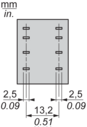
Pin Side View

Symbols shown in blue correspond to Nema marking.
Durability (inductive load) = durability (resistive load) x reduction coefficient.
Resistive AC load

X Switching capacity (kVA)
Y Durability (Number of operating cycles)
A RXM2AB•••
B RXM3AB•••
C RXM4ΑΒ•••
D RXM4GΒ•••
Reduction coefficient for inductive AC load (depending on power factor cos ϕ)

Y Reduction coefficient (A)
Maximum switching capacity on resistive DC load

X Voltage DC
Y Current DC
A RXM2AB•••
B RXM3AB•••
C RXM4ΑΒ•••
D RXM4GΒ•••
Note : These are typical curves, actual durability depends on load, environment, duty cycle, etc.
For inductive load, to increase relay life cycles, please add a proper load protection circuit (eg: RC protection/Varistor/free Wheeling diode -DC load only- ).
For low level loads (below 10mA), we recommend to use RXM*GB series with bifurcated contacts relays instead.
AC Coil Voltage and Operating Temperature under continuous duty

X : Operating temperature (°C)
Y : AC coil voltage (UC)
Need more information? Check our technical FAQs!
Easily find answers to the most frequently asked questions.