
Roll over image to zoom in

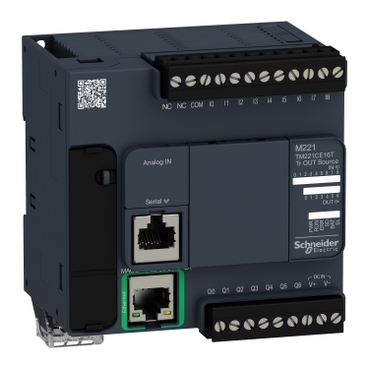
TM221CE16T
Environmental Data
Total lifecycle Carbon footprint
107
Use Better
Packaging made with recycled cardboard
Yes
Use Again
Take-back
No


This TM221 controller is part of the Modicon M221 Logic controller range. It has 16 logic I/O and it is supplied with 24V DC. It is supplied with removable screw terminal blocks for connecting the I/O, a removable screw terminal block for connecting the power supply, a button cell backup battery BR2032 and a cable for connecting the analog inputs. M221 logic controllers have three types of integrated communication port, Ethernet, RS 232/RS 485 serial link and USB mini-B programming port. It enables the control of simple machines. The capacity of M221 logic controllers can be enhanced with the Modicon TM3 expansion module offer.
| Range of product | Modicon M221 |
|---|---|
| Product or component type | Logic controller |
| [Us] rated supply voltage | 24 V DC |
| Discrete input number | 9, discrete input 4 fast input conforming to IEC 61131-2 Type 1 |
| Analogue input number | 2 at 0...10 V |
| Discrete output type | Transistor |
| Discrete output number | 7 transistor 2 fast output |
| Discrete output voltage | 24 V DC |
| Discrete output current | 0.5 A |
| Discrete I/O number | 16 |
|---|---|
| Maximum number of I/O expansion module | 4 (local I/O-Architecture) 11 (remote I/O-Architecture) |
| Supply voltage limits | 20.4…28.8 V |
| Inrush current | 35 A |
| Maximum power consumption in W | 11 W at 24 V (with max number of I/O expansion module) 4.6 W at 24 V (without I/O expansion module) |
| Power supply output current | 0.325 A 5 V for expansion bus 0.15 A 24 V for expansion bus |
| Discrete input logic | Sink or source (positive/negative) |
| Discrete input voltage | 24 V |
| Discrete input voltage type | DC |
| Analogue input resolution | 10 bits |
| LSB value | 10 mV |
| Conversion time | 1 ms per channel + 1 controller cycle time for analogue input analog input |
| Permitted overload on inputs | +/- 30 V DC for 5 min (maximum) for analog input +/- 13 V DC (permanent) for analog input |
| Voltage state 1 guaranteed | >= 15 V for input |
| Voltage state 0 guaranteed | <= 5 V for input |
| Discrete input current | 7 mA for discrete input 5 mA for fast input |
| Input impedance | 3.4 kOhm for discrete input 100 kOhm for analog input 4.9 kOhm for fast input |
| Response time | 35 µs turn-off, I2...I5 terminal(s) for input 5 µs turn-on, I0, I1, I6, I7 terminal(s) for fast input 35 µs turn-on, other terminals terminal(s) for input 5 µs turn-off, I0, I1, I6, I7 terminal(s) for fast input 100 µs turn-off, other terminals terminal(s) for input 5 µs turn-on, turn-off, Q0...Q1 terminal(s) for output 50 µs turn-on, turn-off, Q2...Q3 terminal(s) for output 300 µs turn-on, turn-off, other terminals terminal(s) for output |
| Configurable filtering time | 0 ms for input 3 ms for input 12 ms for input |
| Discrete output logic | Positive logic (source) |
| Maximum current per output common | 3.5 A |
| Output frequency | 100 kHz for fast output (PWM/PLS mode) at Q0...Q1 5 kHz for output at Q2...Q3 0.1 kHz for output at Q4...Q6 |
| Absolute accuracy error | +/- 1 % of full scale for analog input |
| Maximum leakage current | 0.1 mA for transistor output |
| Maximum voltage drop | <1 V |
| Mechanical durability | 20000000 cycles for transistor output |
| Maximum tungsten load | <12 W for output and fast output |
| Protection type | Overload and short-circuit protection at 1 A |
| Reset time | 1 s automatic reset |
| Memory capacity | 256 kB for user application and data RAM with 10000 instructions 256 kB for internal variables RAM |
| Data backed up | 256 kB built-in flash memory for backup of application and data |
| Data storage equipment | 2 GB SD card (optional) |
| Battery type | BR2032 or CR2032X lithium non-rechargeable |
| Backup time | 1 year at 25 °C (by interruption of power supply) |
| Execution time for 1 KInstruction | 0.3 ms for event and periodic task |
| Execution time per instruction | 0.2 µs Boolean |
| Exct time for event task | 60 µs response time |
| Maximum size of object areas | 512 %M memory bits 255 %C counters 512 %KW constant words 255 %TM timers 8000 %MW memory words |
| Realtime clock | With |
| Clock drift | <= 30 s/month at 25 °C |
| Regulation loop | Adjustable PID regulator up to 14 simultaneous loops |
| Positioning functions | Position PTO 2 axe(s)pulse/direction mode (100 kHz) Position PTO 1 axe(s)CW/CCW mode (100 kHz) |
| Function available | PWM Frequency generator PLS |
| Counting input number | 4 fast input (HSC mode) at 100 kHz 32 bits |
| counter function | Single phase A/B Pulse/direction |
| Integrated connection type | USB port with mini B USB 2.0 connector Non isolated serial link serial 1 with RJ45 connector and RS232/RS485 interface Ethernet with RJ45 connector |
| Supply | (serial)serial link supply: 5 V, <200 mA |
| Transmission rate | 1.2...115.2 kbit/s (115.2 kbit/s by default) for bus length of 15 m for RS485 1.2...115.2 kbit/s (115.2 kbit/s by default) for bus length of 3 m for RS232 480 Mbit/s for USB |
| Communication port protocol | USB port: USB - SoMachine-Network Non isolated serial link: Modbus master/slave - RTU/ASCII or SoMachine-Network Ethernet |
| Port Ethernet | 10BASE-T/100BASE-TX 1 port with 100 m copper cable |
| Communication service | Modbus TCP client DHCP client Modbus TCP slave device Modbus TCP server Ethernet/IP adapter |
| Local signalling | 1 LED (green) for PWR 1 LED (green) for RUN 1 LED (red) for module error (ERR) 1 LED (green) for SD card access (SD) 1 LED (red) for BAT 1 LED per channel (green) for I/O state 1 LED (green) for SL Ethernet network activity (green) for ACT Ethernet network link (yellow) for Link (Link Status) |
| Electrical connection | removable screw terminal block for inputs removable screw terminal block for outputs terminal block, 3 terminal(s) for connecting the 24 V DC power supply connector, 4 terminal(s) for analogue inputs Mini B USB 2.0 connector for a programming terminal |
| Maximum cable distance between devices | Shielded cable: <10 m for fast input Unshielded cable: <30 m for output Unshielded cable: <30 m for digital input Unshielded cable: <1 m for analog input Shielded cable: <3 m for fast output |
| Insulation | Between input and internal logic at 500 V AC Between fast input and internal logic at 500 V AC Non-insulated between inputs Between output and internal logic at 500 V AC Non-insulated between analogue input and internal logic Non-insulated between analogue inputs |
| Marking | CE |
| Mounting support | Top hat type TH35-15 rail conforming to IEC 60715 Top hat type TH35-7.5 rail conforming to IEC 60715 plate or panel with fixing kit |
| Height | 90 mm |
| Depth | 70 mm |
| Width | 95 mm |
| Net weight | 0.346 kg |
| Standards | IEC 61131-2 UL 508 CAN/CSA C22.2 No. 213 IACS E10 ANSI/ISA 12-12-01 |
|---|---|
| Product certifications | EAC DNV-GL RCM ABS cULus LR CE UKCA cULus HazLoc |
| Environmental characteristic | Ordinary and hazardous location |
| Resistance to electrostatic discharge | 8 kV in air conforming to IEC 61000-4-2 4 kV on contact conforming to IEC 61000-4-2 |
| Resistance to electromagnetic fields | 10 V/m 80 MHz...1 GHz conforming to IEC 61000-4-3 3 V/m 1.4 GHz...2 GHz conforming to IEC 61000-4-3 1 V/m 2...2.7 GHz conforming to IEC 61000-4-3 |
| Resistance to magnetic fields | 30 A/m 50/60 Hz conforming to IEC 61000-4-8 |
| Resistance to fast transients | 2 kV (power lines) conforming to IEC 61000-4-4 2 kV (relay output) conforming to IEC 61000-4-4 1 kV (I/O) conforming to IEC 61000-4-4 1 kV (Ethernet line) conforming to IEC 61000-4-4 1 kV (serial link) conforming to IEC 61000-4-4 |
| Surge withstand | 2 kV power lines (AC) common mode conforming to IEC 61000-4-5 2 kV relay output common mode conforming to IEC 61000-4-5 1 kV I/O common mode conforming to IEC 61000-4-5 1 kV shielded cable common mode conforming to IEC 61000-4-5 0.5 kV power lines (DC) differential mode conforming to IEC 61000-4-5 1 kV power lines (AC) differential mode conforming to IEC 61000-4-5 1 kV relay output differential mode conforming to IEC 61000-4-5 0.5 kV power lines (DC) common mode conforming to IEC 61000-4-5 |
| Resistance to conducted disturbances | 10 V 0.15...80 MHz conforming to IEC 61000-4-6 3 V 0.1...80 MHz conforming to Marine specification (LR, ABS, DNV, GL) 10 V spot frequency (2, 3, 4, 6.2, 8.2, 12.6, 16.5, 18.8, 22, 25 MHz) conforming to Marine specification (LR, ABS, DNV, GL) |
| Electromagnetic emission | Conducted emissions - test level: 79 dBμV/m QP/66 dBμV/m AV ( power lines (AC)) at 0.15…0.5 MHz conforming to IEC 55011 Conducted emissions - test level: 73 dBμV/m QP/60 dBμV/m AV ( power lines (AC)) at 0.5…300 MHz conforming to IEC 55011 Conducted emissions - test level: 120...69 dBµV/m QP ( power lines) at 10…150 kHz conforming to IEC 55011 Conducted emissions - test level: 63 dBμV/m QP ( power lines) at 1.5…30 MHz conforming to IEC 55011 Radiated emissions - test level: 40 dBμV/m QP class A ( 10 m) at 30…230 MHz conforming to IEC 55011 Conducted emissions - test level: 79...63 dBμV/m QP ( power lines) at 150…1500 kHz conforming to IEC 55011 Radiated emissions - test level: 47 dBμV/m QP class A ( 10 m) at 200…1000 MHz conforming to IEC 55011 |
| Immunity to microbreaks | 10 ms |
| Ambient air temperature for operation | -10…55 °C (horizontal installation) -10…35 °C (vertical installation) |
| Ambient air temperature for storage | -25…70 °C |
| Relative humidity | 10…95 %, without condensation (in operation) 10…95 %, without condensation (in storage) |
| IP degree of protection | IP20 with protective cover in place |
| Pollution degree | <= 2 |
| Operating altitude | 0...2000 m |
| Storage altitude | 0…3000 m |
| Vibration resistance | 3.5 mm at 5…8.4 Hz on symmetrical rail 3.5 mm at 5…8.4 Hz on panel mounting 1 gn at 8.4…150 Hz on symmetrical rail 1 gn at 8.4…150 Hz on panel mounting |
| Shock resistance | 147 m/s² for 11 ms |
| Unit Type of Package 1 | PCE |
|---|---|
| Number of Units in Package 1 | 1 |
| Package 1 Height | 10.6 cm |
| Package 1 Width | 14.0 cm |
| Package 1 Length | 13.9 cm |
| Package 1 Weight | 300.0 g |
| Unit Type of Package 2 | S04 |
| Number of Units in Package 2 | 20 |
| Package 2 Height | 30 cm |
| Package 2 Width | 40 cm |
| Package 2 Length | 60 cm |
| Package 2 Weight | 6.983 kg |
| Unit Type of Package 3 | P12 |
| Number of Units in Package 3 | 240 |
| Package 3 Height | 105.0 cm |
| Package 3 Width | 120.0 cm |
| Package 3 Length | 80.0 cm |
| Package 3 Weight | 156 kg |
Schneider Electric aims to achieve Net Zero status by 2050 through supply chain partnerships, lower impact materials, and circularity via our ongoing “Use Better, Use Longer, Use Again” campaign to extend product lifetimes and recyclability.
Total lifecycle Carbon footprint
107
Environmental Disclosure
Use Better
Packaging made with recycled cardboard
Yes
Packaging without single use plastic
Yes
Pro-active compliance (Product out of EU RoHS legal scope)
SCIP Number
C9e48184-76ce-4d1a-abc2-18108c652781
REACh Regulation
PVC free
Yes
Use Again
End of life manual availability
Take-back
No
WEEE Label
The product must be disposed on European Union markets following specific waste collection and never end up in rubbish bins
Dimensions
Mounting on a Rail

Direct Mounting on a Panel Surface

(1)
Install a mounting strip
Mounting Hole Layout
Mounting
Correct Mounting Position

Acceptable Mounting Position

Incorrect Mounting Position
Clearance

Digital Inputs
(*)
Type T fuse
(A)
Sink wiring (positive logic).
(B)
Source wiring (negative logic).
Connection of the Fast Inputs

I0, I1, I6, I7
Transistor Outputs
(*)
Type T fuse
Connection of the Fast Outputs

Q0, Q1
Analog Inputs


The (-) poles are connected internally.
Pin | Wire Color |
|---|---|
0 V | Black |
AN1 | Red |
0 V | Black |
AN0 | Red |
Ethernet Connection

Pin N° | Signal |
|---|---|
1 | TD+ |
2 | TD- |
3 | RD+ |
4 | - |
5 | - |
6 | RD- |
7 | - |
8 | - |

USB Mini-B Connection

SL1 Connection

SL1
N ° | RS 232 | RS 485 |
|---|---|---|
1 | RxD | N.C. |
2 | TxD | N.C. |
3 | RTS | N.C. |
4 | N.C. | D1 |
5 | N.C. | D0 |
6 | CTS | N.C. |
7 | N.C*. | 5 Vdc |
8 | Common | Common |
N.C.: not connected
* : 5 Vdc delivered by the controller. Do not connect.

Derating Curves
Embedded Digital Inputs (No Cartridge)

X :
Ambient temperature
Y :
Input simultaneous ON ratio
Embedded Digital Inputs (with Cartridge)

X :
Ambient temperature
Y :
Input simultaneous ON ratio
Derating Curves
Embedded Digital Outputs (No Cartridge)
X :
Ambient temperature
Y :
Output simultaneous ON ratio
Embedded Digital Outputs (with Cartridge)
X :
Ambient temperature
Y :
Output simultaneous ON ratio
Need more information? Check our technical FAQs!
Easily find answers to the most frequently asked questions.