
Roll over image to zoom in

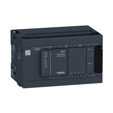
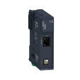
TM241C24U
Environmental Data
Total lifecycle Carbon footprint
912
Use Better
Packaging made with recycled cardboard
Yes
Use Again
Take-back
No


Compatible Software

controller M241 24 IO transistor NPN This product is part of the Modicon M241 range, an offer of plc controllers for performance demanding applications. This logic controller provides 14 discrete, 8 fast inputs, 10 transistor, 4 fast outputs with NPN transistor output. It is a Modicon logic controller with a rated supply/output voltage of 24V DC, an output current of 0.5A for transistor output, 0.1A for fast with sink or source input logic positive output logic. This product enables to build application intuitively as never before due to an organised screen design. Integrated connections are USB port with mini B USB 2.0 connector, non isolated serial link 1 with RJ45 connector and RS232/RS485 interface and non isolated serial link 2 with removable screw terminal block connector and RS485 interface. It is a Modicon M241 controller with 8MB for program, 64MB for system memory RAM, 128MB built-in flash memory for backup of user programs and a SD card memory capacity of 16GB. It is an IP20 rated product. Its dimensions are 150mm (Width) x 95mm (Depth) x 90mm (Height). It weighs 0.53kg. The Modicon M241 logic controllers are designed for high-performance compact machines incorporating speed and position control functions. This product is certified by CE, IACS E10, CSA, RCM and CULus. It meets ANSI/ISA 12-12-01, CSA C22.2 No 142, CSA C22.2 No 213, EN/IEC 61131-22007, marine specification (LR, ABS, DNV, GL), UL 1604 and UL 508 standards. The TM3 I/O bus port embedded on the Modicon M241 logic controllers allows the connection of Modicon TM3 expansion modules for local, remote and distributed I/O configurations, programmed with EcoStruxure Machine Expert software. It supports DIN rail mount.
| Range of product | Modicon M241 |
|---|---|
| Product or component type | Logic controller |
| [Us] rated supply voltage | 24 V DC |
| Discrete input number | 14, discrete input 8 fast input conforming to IEC 61131-2 Type 1 |
| Discrete output type | Transistor |
| Discrete output number | 10 transistor 4 fast output |
| Discrete output voltage | 24 V DC for transistor output |
| Discrete output current | 0.5 A for transistor output (Q0...Q9) 0.1 A for fast output (PTO mode) (Q0...Q3) |
| Discrete I/O number | 24 |
|---|---|
| Maximum number of I/O expansion module | 7 (local I/O-Architecture) 14 (remote I/O-Architecture) |
| Supply voltage limits | 20.4…28.8 V |
| Inrush current | 50 A |
| Power consumption in W | 32.6…40.4 W (with max number of I/O expansion module) |
| Discrete input logic | Sink or source |
| Discrete input voltage | 24 V |
| Discrete input voltage type | DC |
| Voltage state 1 guaranteed | >= 15 V for input |
| Voltage state 0 guaranteed | <= 5 V for input |
| Discrete input current | 5 mA for input 10.7 mA for fast input |
| Input impedance | 4.7 kOhm for input 2.81 kOhm for fast input |
| Response time | 50 µs turn-on, I0...I13 terminal(s) for input 50 µs turn-off, I0...I13 terminal(s) for input <= 2 µs turn-on, I0...I7 terminal(s) for fast input <= 2 µs turn-off, I0...I7 terminal(s) for fast input <= 34 µs turn-on, Q0...Q9 terminal(s) for output <= 250 µs turn-off, Q0...Q9 terminal(s) for output <= 2 µs turn-on, Q0...Q3 terminal(s) for fast output <= 2 µs turn-off, Q0...Q3 terminal(s) for fast output |
| Configurable filtering time | 1 s for fast input 12 ms for fast input 0 ms for input 1 ms for input 4 ms for input 12 ms for input |
| Discrete output logic | Negative logic (sink) |
| Output voltage limits | 30 V DC |
| Maximum current per output common | 2 A with Q0...Q3 for fast output 2 A with Q4...Q7 for output 1 A with Q8...Q9 for output |
| Maximum output frequency | 20 kHz for fast output (PWM mode) 100 kHz for fast output (PLS mode) 1 kHz for output |
| Accuracy | +/- 0.1 % at 0.02…0.1 kHz for fast output +/- 1 % at 0.1…1 kHz for fast output |
| Maximum leakage current | 5 µA for output |
| Maximum voltage drop | <1 V |
| Maximum tungsten load | <2.4 W |
| Protection type | Short-circuit protection Short-circuit and overload protection with automatic reset Reverse polarity protection for fast output |
| Reset time | 10 ms automatic reset output 12 s automatic reset fast output |
| Memory capacity | 64 MB for system memory RAM |
| Data backed up | 128 MB built-in flash memory for backup of user programs |
| Data storage equipment | <= 16 GB SD card (optional) |
| Battery type | BR2032 lithium non-rechargeable, battery life: 4 year(s) |
| Backup time | 2 years at 25 °C |
| Execution time for 1 KInstruction | 0.3 ms for event and periodic task 0.7 ms for other instruction |
| Application structure | 4 cyclic master tasks 8 external event tasks 8 event tasks 3 cyclic master tasks + 1 freewheeling task |
| Realtime clock | With |
| Clock drift | <= 60 s/month at 25 °C |
| Positioning functions | PTO function 4 channel(s) (positioning frequency: 100 kHz) PTO function 4 channel(s) for transistor output (positioning frequency: 1 kHz) |
| Counting input number | 4 fast input (HSC mode) at 200 kHz 14 standard input at 1 kHz |
| Control signal type | A/B at 100 kHz for fast input (HSC mode) Pulse/direction at 200 kHz for fast input (HSC mode) Single phase at 200 kHz for fast input (HSC mode) |
| Integrated connection type | Non isolated serial link serial 1 with RJ45 connector and RS232/RS485 interface Non isolated serial link serial 2 with removable screw terminal block connector and RS485 interface USB port with mini B USB 2.0 connector |
| Supply | (serial 1)serial link supply: 5 V, <200 mA |
| Transmission rate | 1.2...115.2 kbit/s (115.2 kbit/s by default) for bus length of 15 m for RS485 1.2...115.2 kbit/s (115.2 kbit/s by default) for bus length of 3 m for RS232 480 Mbit/s for bus length of 3 m for USB |
| Communication port protocol | Non isolated serial link: Modbus master/slave |
| Local signalling | 1 LED (green) for PWR 1 LED (green) for RUN 1 LED (red) for module error (ERR) 1 LED (red) for I/O error (I/O) 1 LED (green) for SD card access (SD) 1 LED (red) for BAT 1 LED (green) for SL1 1 LED (green) for SL2 1 LED (red) for bus fault on TM4 (TM4) 1 LED per channel (green) for I/O state |
| Electrical connection | removable screw terminal blockfor inputs and outputs (pitch 5.08 mm) removable screw terminal blockfor connecting the 24 V DC power supply (pitch 5.08 mm) |
| Maximum cable distance between devices | Unshielded cable: <50 m for input Shielded cable: <10 m for fast input Unshielded cable: <50 m for output Shielded cable: <3 m for fast output |
| Insulation | Between supply and internal logic at 500 V AC Non-insulated between supply and ground Between input and internal logic at 500 V AC Non-insulated between inputs Between fast input and internal logic at 500 V AC Between output and internal logic at 500 V AC Non-insulated between outputs Between fast output and internal logic at 500 V AC |
| Marking | CE |
| Surge withstand | 1 kV power lines (DC) common mode conforming to IEC 61000-4-5 1 kV shielded cable common mode conforming to IEC 61000-4-5 0.5 kV power lines (DC) differential mode conforming to IEC 61000-4-5 1 kV relay output differential mode conforming to IEC 61000-4-5 1 kV input common mode conforming to IEC 61000-4-5 1 kV transistor output common mode conforming to IEC 61000-4-5 |
| Mounting support | Top hat type TH35-15 rail conforming to IEC 60715 Top hat type TH35-7.5 rail conforming to IEC 60715 plate or panel with fixing kit |
| Height | 90 mm |
| Depth | 95 mm |
| Width | 150 mm |
| Net weight | 0.53 kg |
| Standards | ANSI/ISA 12-12-01 CSA C22.2 No 142 CSA C22.2 No 213 IEC 61131-2:2007 Marine specification (LR, ABS, DNV, GL) UL 508 |
|---|---|
| Product certifications | RCM cULus CE UKCA DNV-GL ABS LR |
| Resistance to electrostatic discharge | 8 kV in air conforming to IEC 61000-4-2 4 kV on contact conforming to IEC 61000-4-2 |
| Resistance to electromagnetic fields | 10 V/m 80 MHz...1 GHz conforming to IEC 61000-4-3 3 V/m 1.4 GHz...2 GHz conforming to IEC 61000-4-3 1 V/m 2 GHz...3 GHz conforming to IEC 61000-4-3 |
| Resistance to fast transients | 2 kV (power lines) conforming to IEC 61000-4-4 1 kV (serial link) conforming to IEC 61000-4-4 1 kV (input) conforming to IEC 61000-4-4 1 kV (transistor output) conforming to IEC 61000-4-4 |
| Resistance to conducted disturbances | 10 V 0.15...80 MHz conforming to IEC 61000-4-6 3 V 0.1...80 MHz conforming to Marine specification (LR, ABS, DNV, GL) 10 V spot frequency (2, 3, 4, 6.2, 8.2, 12.6, 16.5, 18.8, 22, 25 MHz) conforming to Marine specification (LR, ABS, DNV, GL) |
| Electromagnetic emission | Conducted emissions - test level: 120...69 dBµV/m QP ( power lines) at 10…150 kHz conforming to IEC 55011 Conducted emissions - test level: 63 dBμV/m QP ( power lines) at 1.5…30 MHz conforming to IEC 55011 Radiated emissions - test level: 40 dBμV/m QP class A at 30…230 MHz conforming to IEC 55011 Conducted emissions - test level: 79...63 dBμV/m QP ( power lines) at 150…1500 kHz conforming to IEC 55011 Radiated emissions - test level: 47 dBμV/m QP class A at 230…1000 MHz conforming to IEC 55011 |
| Immunity to microbreaks | 10 ms |
| Ambient air temperature for operation | -10…50 °C (vertical installation) -10…55 °C (horizontal installation) |
| Ambient air temperature for storage | -25…70 °C |
| Relative humidity | 10…95 %, without condensation (in operation) 10…95 %, without condensation (in storage) |
| IP degree of protection | IP20 with protective cover in place |
| Pollution degree | 2 |
| Operating altitude | 0...2000 m |
| Storage altitude | 0…3000 m |
| Vibration resistance | 3.5 mm at 5…8.4 Hz on symmetrical rail 3 gn at 8.4…150 Hz on symmetrical rail 3.5 mm at 5…8.4 Hz on panel mounting 3 gn at 8.4…150 Hz on panel mounting |
| Shock resistance | 15 gn for 11 ms |
| Unit Type of Package 1 | PCE |
|---|---|
| Number of Units in Package 1 | 1 |
| Package 1 Height | 12.8 cm |
| Package 1 Width | 11.45 cm |
| Package 1 Length | 18.6 cm |
| Package 1 Weight | 799.0 g |
| Unit Type of Package 2 | S03 |
| Number of Units in Package 2 | 12 |
| Package 2 Height | 30 cm |
| Package 2 Width | 30 cm |
| Package 2 Length | 40 cm |
| Package 2 Weight | 9.588 kg |
Schneider Electric aims to achieve Net Zero status by 2050 through supply chain partnerships, lower impact materials, and circularity via our ongoing “Use Better, Use Longer, Use Again” campaign to extend product lifetimes and recyclability.
Total lifecycle Carbon footprint
912
Environmental Disclosure
Use Better
Packaging made with recycled cardboard
Yes
Packaging without single use plastic
Yes
Pro-active compliance (Product out of EU RoHS legal scope)
SCIP Number
3d1fb974-648d-4978-8c59-b7dcc486f5a5
REACh Regulation
PVC free
Yes
Use Again
End of life manual availability
Take-back
No
WEEE Label
The product must be disposed on European Union markets following specific waste collection and never end up in rubbish bins
Dimensions

Clearance

Mounting Position

Acceptable Mounting

NOTE: Expansion modules must be mounted above the logic controller.
Incorrect Mounting

Direct Mounting On a Panel Surface
Mounting Hole Layout

Digital Inputs
Wiring Diagram
(*) :
Type T fuse
(1) :
The COM0, COM1 and COM2 terminals are not connected internally
(A) :
Sink wiring (positive logic)
(B) :
Source wiring (negative logic)
Fast Input Wiring (I0...I7)

Fast Transistor Outputs
Wiring Diagram
(*) :
Type T fuse
(1)
The V0+, V1+, V2+ and V3+ terminals are not connected internally.
(2)
The V0-, V1-, V2- and V3- terminals are not connected internally.
Transistor Outputs
Wiring Diagram
(*) :
Type T fuse
(1) :
The V1+ and V2+ terminals are not connected internally.
(2) :
The V1– and V2– terminals are not connected internally.
USB Mini-B Connection

Items usually bought together

Need more information? Check our technical FAQs!
Easily find answers to the most frequently asked questions.