
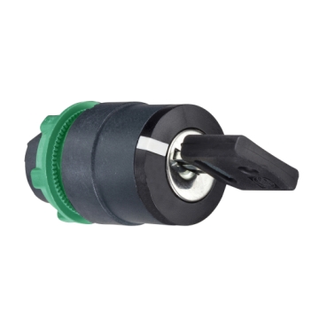


ZB5AG2
Key withdrawal position:
Operator position information:
Type of operator:
Return:


| Range of product | Harmony XB5 Harmony XALF |
|---|---|
| Product or component type | Head for key selector switch |
| Device short name | ZB5 |
| Bezel material | Dark grey plastic |
| Mounting diameter | 22 mm |
| Head type | Standard |
| Sale per indivisible quantity | 1 |
| Shape of signaling unit head | Round |
| Type of operator | stay put |
| Operator profile | Black key switch |
| Operator position information | 2 positions 90° |
| Type of keylock | Key 455 |
| Key withdrawal position | Left |
| CAD overall width | 29 mm |
|---|---|
| CAD overall height | 29 mm |
| CAD overall depth | 72 mm |
| Net weight | 0.057 kg |
| Mechanical durability | 1000000 cycles |
| Station name | XALD 1...5 cut-outs XALK 2...5 cut-outs |
| Electrical composition code | C4 for <6 contacts using single and double blocks in front mounting C5 for <5 contacts using single blocks in front mounting C6 for <5 contacts using single and double blocks in front mounting C7 for <4 contacts using single blocks in front mounting C8 for <4 contacts using single and double blocks in front mounting C11 for <3 contacts using single blocks in front mounting C3 for <6 contacts using single blocks in front mounting SF1 for <3 contacts using single blocks in front mounting SR1 for <3 contacts using single blocks in rear mounting C15 for <1 contacts using single blocks in front mounting |
| Device presentation | Basic element |
| Protective treatment | TH |
|---|---|
| Ambient air temperature for storage | -40…70 °C |
| Ambient air temperature for operation | -40…70 °C |
| Overvoltage category | Class II conforming to IEC 60536 |
| IP degree of protection | IP66 conforming to IEC 60529 IP67 IP69 IP69K |
| NEMA degree of protection | NEMA 13 NEMA 4X |
| Resistance to high pressure washer | 7000000 Pa at 55 °C, distance : 0.1 m |
| IK degree of protection | IK06 conforming to IEC 50102 |
| Standards | UL 508 IEC 60947-5-1 IEC 60947-1 CSA C22.2 No 14 JIS C8201-5-1 IEC 60947-5-4 JIS C8201-1 |
| Product certifications | DNV CSA BV LROS (Lloyds register of shipping) UL listed |
| Vibration resistance | 5 gn (f= 2…500 Hz) conforming to IEC 60068-2-6 |
| Shock resistance | 30 gn (duration = 18 ms) for half sine wave acceleration conforming to IEC 60068-2-27 50 gn (duration = 11 ms) for half sine wave acceleration conforming to IEC 60068-2-27 |
| Unit Type of Package 1 | PCE |
|---|---|
| Number of Units in Package 1 | 1 |
| Package 1 Height | 3.500 cm |
| Package 1 Width | 5.400 cm |
| Package 1 Length | 8.900 cm |
| Package 1 Weight | 66.000 g |
| Unit Type of Package 2 | BB1 |
| Number of Units in Package 2 | 5 |
| Package 2 Height | 8.800 cm |
| Package 2 Width | 5.200 cm |
| Package 2 Length | 26.500 cm |
| Package 2 Weight | 343.000 g |
| Unit Type of Package 3 | S03 |
| Number of Units in Package 3 | 150 |
| Package 3 Height | 30.000 cm |
| Package 3 Width | 30.000 cm |
| Package 3 Length | 40.000 cm |
| Package 3 Weight | 10.800 kg |
| Warranty | 12 months |
|---|


(1) Diameter on finished panel or support
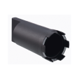
(2) For selector switches and Emergency stop buttons, use of an anti-rotation plate type ZB5AZ902 is recommended.
(3) Ø22.5 mm recommended (Ø22.3 0+0.4) / Ø0.89 in. recommended (Ø0.88 in. 0+0.016)
Connections | a in mm | a in in. | b in mm | b in in. |
|---|---|---|---|---|
By screw clamp terminals or plug-in connector | 40 | 1.57 | 30 | 1.18 |
By Faston connectors | 45 | 1.77 | 32 | 1.26 |
On printed circuit board | 30 | 1.18 | 30 | 1.18 |

(1) Diameter on finished panel or support
(2) For selector switches and Emergency stop buttons, use of an anti-rotation plate type ZB5AZ902 is recommended.
(3) Ø22.5 mm recommended (Ø22.3 0+0.4) / Ø0.89 in. recommended (Ø0.88 in. 0+0.016)

A: 30 mm min. / 1.18 in. min.
B: 40 mm min. / 1.57 in. min.
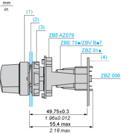
Dimensions in mm
A: 30 mm min.
B: 40 mm min.
Dimensions in in.
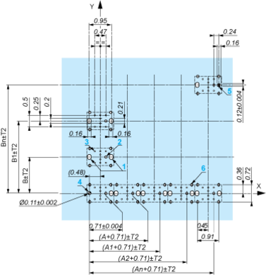
A: 1.18 in. min.
B: 1.57 in. min.
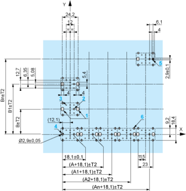
The cumulative tolerance must not exceed 0.3 mm / 0.012 in.: T1 + T2 = 0.3 mm max.
Minimum thickness of circuit board: 1.6 mm / 0.06 in.
Cut-out diameter: 22.4 mm ± 0.1 / 0.88 in. ± 0.004
Orientation of body/fixing collar ZB5AZ009: ± 2°30’ (excluding cut-outs marked a and b).
Tightening torque of screws ZBZ006: 0.6 N.m (5.3 lbf.in) max.
Allow for one ZB5AZ079 fixing collar/pillar and its fixing screws:
every 90 mm / 3.54 in. horizontally (X), and 120 mm / 4.72 in. vertically (Y).
with each selector switch head (ZB5AD•, ZB5AJ•, ZB5AG•).
The fixing centers marked a and b are diagonally opposed and must align with those marked 4 and 5.
(1) Head ZB5AD•
(2) Panel
(2) Nut
(4) Printed circuit board
1 2 elongated holes for ZBZ006 screw access
2 1 hole Ø 2.4 mm ± 0.05 / 0.09 in. ± 0.002 for centring adapter ZBZ01•
3 8 × Ø 1.2 mm / 0.05 in. holes
4 1 hole Ø 2.9 mm ± 0.05 / 0.11 in. ± 0.002, for aligning the printed circuit board (with cut-out marked a)
5 1 elongated hole for aligning the printed circuit board (with cut-out marked b)
6 4 holes Ø 2.4 mm / 0.09 in. for clipping in adapter ZBZ01•
Dimensions An + 18.1 relate to the Ø 2.4 mm ± 0.05 / 0.09 in. ± 0.002 holes for centring adapter ZBZ01•.


Single contact

Double contact

Light block

Possible location


Push | Position | Top |
| ||
Bottom |
|
|
| ||
Location | Left | Centre | Right | ||
State | 0 | 0 | 0 | ||
Contacts | N/O | open | open | open | |
N/C | closed | closed | closed | ||


Push | Position | Top | |||
Bottom |
| ||||
Location | Left | Centre | Right | ||
State | 1 | 1 | 1 | ||
Contacts | N/O | closed | closed | closed | |
N/C | open | open | open | ||
Items usually bought together


Need more information? Check our technical FAQs!
Easily find answers to the most frequently asked questions.