
Roll over image to zoom in


+ 5
1 videos
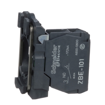
ZB5AZ101
Contacts type and composition:
Environmental Data
Total lifecycle Carbon footprint
1
Use Better
Packaging made with recycled cardboard
Yes
Use Again
Take-back
No

This Harmony XB5, single contact block uses screw clamp terminals. This contact block allows fast and easy replacement and configuration of your push buttons and selector switches. It is easily installed and replaced on XB5 complete push-button units and selector switches via a clip assembly and connects to control circuits with simple screw-clamp connections. It protects operators from unexpected contact with live circuits thanks to its IP20 protection index. The base unit to start assembling your plastic push-button or switch. Its wide range of operating temperatures from -40°C to 70°C allows versatility in usage of product. Vibration resistant screw clamp connection terminals ensure high vibration resistance making product suitable installation on high impact machine.


| Range of product | Harmony XB5 |
|---|---|
| Product or component type | Complete body/contact assembly |
| Device short name | ZB5 |
| Fixing collar material | Plastic |
| Sale per indivisible quantity | 1 |
| Head type | Standard |
| Contacts type and composition | 1 NO |
| Contact operation | Slow-break |
| Contact block type | Single |
| Connections - terminals | Screw clamp terminals, <= 2 x 1.5 mm² with cable end conforming to IEC 60947-1 Screw clamp terminals, >= 1 x 0.22 mm² without cable end conforming to IEC 60947-1 |
| CAD overall width | 30 mm |
|---|---|
| CAD overall height | 42 mm |
| CAD overall depth | 32 mm |
| Terminals description ISO n°1 | (13-14)NO |
| Net weight | 0.021 kg |
| Device composition | Fixing collar Body |
| Contacts usage | Standard contacts |
| Positive opening | Without |
| Operating travel | 2.6 mm (NO changing electrical state) 4.3 mm (total travel) |
| Operating force | 2.3 N NO changing electrical state |
| Mechanical durability | 10000000 cycles |
| Tightening torque | 0.8…1.2 N.m conforming to IEC 60947-1 |
| Shape of screw head | Cross compatible with Philips no 1 screwdriver Cross compatible with pozidriv No 1 screwdriver Slotted compatible with flat Ø 4 mm screwdriver Slotted compatible with flat Ø 5.5 mm screwdriver |
| Contacts material | Silver alloy (Ag/Ni) |
| Short-circuit protection | 10 A cartridge fuse type gG conforming to IEC 60947-5-1 |
| [Ith] conventional free air thermal current | 10 A conforming to IEC 60947-5-1 |
| [Ui] rated insulation voltage | 600 V (pollution degree 3) conforming to IEC 60947-1 |
| [Uimp] rated impulse withstand voltage | 6 kV conforming to IEC 60947-1 |
| [Ie] rated operational current | 3 A at 240 V, AC-15, A600 conforming to IEC 60947-5-1 6 A at 120 V, AC-15, A600 conforming to IEC 60947-5-1 0.1 A at 600 V, DC-13, Q600 conforming to IEC 60947-5-1 0.27 A at 250 V, DC-13, Q600 conforming to IEC 60947-5-1 0.55 A at 125 V, DC-13, Q600 conforming to IEC 60947-5-1 1.2 A at 600 V, AC-15, A600 conforming to IEC 60947-5-1 |
| Electrical durability | 1000000 cycles, AC-15, 2 A at 230 V, operating rate <3600 cyc/h, load factor: 0.5 conforming to IEC 60947-5-1 appendix C 1000000 cycles, AC-15, 3 A at 120 V, operating rate <3600 cyc/h, load factor: 0.5 conforming to IEC 60947-5-1 appendix C 1000000 cycles, AC-15, 4 A at 24 V, operating rate <3600 cyc/h, load factor: 0.5 conforming to IEC 60947-5-1 appendix C 1000000 cycles, DC-13, 0.2 A at 110 V, operating rate <3600 cyc/h, load factor: 0.5 conforming to IEC 60947-5-1 appendix C 1000000 cycles, DC-13, 0.5 A at 24 V, operating rate <3600 cyc/h, load factor: 0.5 conforming to IEC 60947-5-1 appendix C |
| Electrical reliability | Λ < 10exp(-6) at 5 V, 1 mA in clean environment conforming to IEC 60947-5-4 Λ < 10exp(-8) at 17 V, 5 mA in clean environment conforming to IEC 60947-5-4 |
| Device presentation | Basic sub-assemblies |
| Protective treatment | TH |
|---|---|
| Ambient air temperature for storage | -40…70 °C |
| Ambient air temperature for operation | -40…70 °C |
| IP degree of protection | IP20 conforming to IEC 60529 |
| Standards | UL 508 IEC 60947-5-1 CSA C22.2 No 14 IEC 60947-5-4 IEC 60947-1 JIS C8201-5-1 JIS C8201-1 |
| Product certifications | BV UL CSA DNV LROS (Lloyds register of shipping) |
| Vibration resistance | 5 gn (f= 2…500 Hz) conforming to IEC 60068-2-6 |
| Shock resistance | 30 gn (duration = 18 ms) for half sine wave acceleration conforming to IEC 60068-2-27 50 gn (duration = 11 ms) for half sine wave acceleration conforming to IEC 60068-2-27 |
| Unit Type of Package 1 | PCE |
|---|---|
| Number of Units in Package 1 | 1 |
| Package 1 Height | 4.500 cm |
| Package 1 Width | 3.400 cm |
| Package 1 Length | 5.400 cm |
| Package 1 Weight | 20.000 g |
| Unit Type of Package 2 | S03 |
| Number of Units in Package 2 | 300 |
| Package 2 Height | 30.000 cm |
| Package 2 Width | 30.000 cm |
| Package 2 Length | 40.000 cm |
| Package 2 Weight | 6.530 kg |
| Unit Type of Package 3 | P06 |
| Number of Units in Package 3 | 2400 |
| Package 3 Height | 75.000 cm |
| Package 3 Width | 60.000 cm |
| Package 3 Length | 80.000 cm |
| Package 3 Weight | 62.684 kg |
| Warranty | 12 months |
|---|
Schneider Electric aims to achieve Net Zero status by 2050 through supply chain partnerships, lower impact materials, and circularity via our ongoing “Use Better, Use Longer, Use Again” campaign to extend product lifetimes and recyclability.
Total lifecycle Carbon footprint
1
Environmental Disclosure
Use Better
Packaging made with recycled cardboard
Yes
Packaging without single use plastic
Yes
Pro-active compliance (Product out of EU RoHS legal scope)
REACh Regulation
Use Again
End of life manual availability
Take-back
No
WEEE Label
The product must be disposed on European Union markets following specific waste collection and never end up in rubbish bins
Dimensions
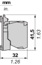
Panel Cut-out for Pushbuttons, Switches and Pilot Lights (Finished Holes, Ready for Installation)
Connection by Screw Clamp Terminals or Plug-in Connectors or on Printed Circuit Board

(1) Diameter on finished panel or support
(2) For selector switches and Emergency stop buttons, use of an anti-rotation plate type ZB5AZ902 is recommended.
(3) Ø22.5 mm recommended (Ø22.3 0+0.4) / Ø0.89 in. recommended (Ø0.88 in. 0+0.016)
Connections | a in mm | a in in. | b in mm | b in in. |
|---|---|---|---|---|
By screw clamp terminals or plug-in connector | 40 | 1.57 | 30 | 1.18 |
By Faston connectors | 45 | 1.77 | 32 | 1.26 |
On printed circuit board | 30 | 1.18 | 30 | 1.18 |
Detail of Lug Recess

(1) Diameter on finished panel or support
(2) For selector switches and Emergency stop buttons, use of an anti-rotation plate type ZB5AZ902 is recommended.
(3) Ø22.5 mm recommended (Ø22.3 0+0.4) / Ø0.89 in. recommended (Ø0.88 in. 0+0.016)
Items usually bought together


Need more information? Check our technical FAQs!
Easily find answers to the most frequently asked questions.