
Roll over image to zoom in


+ 2
2 videos
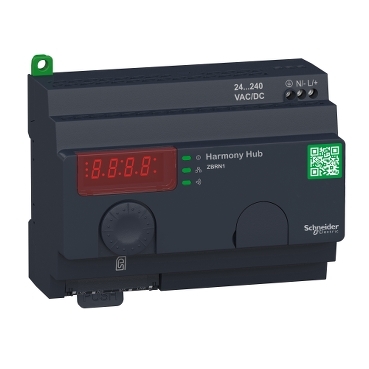
ZBRN1
Product or component type:
Environmental Data
Total lifecycle Carbon footprint
3
Use Better
Packaging made with recycled cardboard
Yes
Use Again
Take-back
No


This configurable harmony Hub is part of the ranges Harmony XB5R plastic and XB4R metal wireless and batteryless pushbuttons. It provides network connectivity openness by operating as an intermediate equipment between the wireless devices and PLCs (Programmable Logic Controller) or industrial PCs (IT/OT box) that support Modbus/TCP protocols. It is equiped with 7 segment display, jog dial, 8 indicating LEDs (Power On, functions mode, communication status, signal strength) external antenna connector and protective plug. It features 1 slot for communication module ZBRCETH (should be ordered separately). It weighs 270g.
| Range of product | Harmony |
|---|---|
| Product or component type | Harmony Hub Wireless/Ethernet gateway |
| Device short name | ZBRN1 |
| Product specific application | Wireless Schneider Electric devices ecosystem |
| Function of module | Zigbee green power gateway |
| Communication port protocol | Modbus/TCP client application, with ZBRCETH module |
| Antenna type | Integrated |
| Transmission frequency | 2405…2480 MHz |
| Maximum radio communication distance | 100 m in free field 250 m if a relay antenna is located between the transmitter and Harmony Hub 60 m if an external antenna is connected to Harmony Hub 25 m with Harmony Hub installed in a metal housing or in a closed metal enclosure |
|---|---|
| Radio response time | < 30 ms |
| Radio channels utilisation | <= 60 devices |
| [Us] rated supply voltage | 24...240 V AC/DC 50/60 Hz - 10...10 % |
| Immunity to microbreaks | 10 ms |
| Maximum power consumption in W | 4 W AC/DC |
| Control circuit frequency | 50...60 Hz +/- 10 % |
| Short-circuit protection | 16 A GB2 circuit breaker |
| Operating position | Any position |
| Mounting support | 35 mm symmetrical DIN rail conforming to IEC 60715 Mounting plate |
| Electrical connection | 1 conductor cable 0.2…4 mm² - AWG 24...AWG 12 - solid - without cable end conforming to IEC 60947-1 2 conductors cable 0.2…1.5 mm² - AWG 24...AWG 16 - solid - without cable end conforming to IEC 60947-1 1 conductor cable 0.2…0.75 mm² - AWG 24...AWG 14 - flexible - with cable end conforming to IEC 60947-1 2 conductors cable 0.2…2.5 mm² - AWG 24...AWG 18 - flexible - with cable end conforming to IEC 60947-1 |
| Tightening torque | 0.35…0.4 N.m conforming to IEC 60947-1 0.35…0.40 N.m conforming to IEC 60947-1 |
| Housing material | Self-extinguishing plastic |
| Status LED | 1 LED green for power ON 1 LED yellow for communication network 5 LEDs red for function mode 1 LED green and yellow for reception signal |
| Rated short-duration power frequency withstand voltage | 1.5 kV 50 Hz conforming to IEC 60947-5-1 |
| [Uimp] rated impulse withstand voltage | 4 kV |
| Surge withstand | 1 kV differential mode conforming to IEC 61000-4-5 2 kV common mode conforming to IEC 61000-4-5 |
| Width | 122 mm |
| Height | 90 mm |
| Depth | 60 mm |
| Net weight | 0.26 kg |
| Antenna gain | 0 dBi |
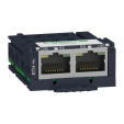
| Integrated connection type | Ethernet Modbus TCP/IP RJ45 Modbus TCP network, 10/100 Mbit/s, 2 twisted pairs |
| Data storage equipment | SD card |
| Topology | Devices linked by daisy-chaining or tap junctions |
| Port Ethernet | 10BASE-T/100BASE-T |
| Maximum cable distance between devices | 1000 m |
| Radio agreement | ANATEL, type III conforming to ETSI EN 301 489-3 FCC, category 2 conforming to ETSI EN 300 440-1 ICASA RSS, category 1 conforming to ETSI EN 300 440-1 SRRC |
|---|---|
| Product certifications | C-Tick CCC CSA GOST UL CE |
| Directives | 2004/108/EC - electromagnetic compatibility 1999/5/EC - R&TTE directive 2006/95/EC - low voltage directive |
| Standards | ETSI EN 300 328 IEC 61131-2 CSA C22.2 No 14 ETSI EN 300 440-2 UL 508 IEC 60950-1 IEC 62311 |
| Ambient air temperature for storage | -40…70 °C |
| Relative humidity | 90 % at -25…55 °C, without condensation conforming to ETSI EN 300 440-1 |
| Operating altitude | 0...2000 m |
| Storage altitude | 0…3000 m |
| Vibration resistance | +/- 3.5 mm (f = 5…14 Hz) conforming to IEC 60068-2-6 1 gn (f = 5…150 Hz) on panel mounting conforming to IEC 60068-2-6 2 gn (f = 8…150 Hz) on DIN rail conforming to IEC 60068-2-6 |
| Shock resistance | 10 gn (duration = 16 ms) for 6000 shocks conforming to IEC 60068-2-27 |
| IP degree of protection | IP20 (casing) conforming to IEC 60529 IP20 (terminals) |
| Pollution degree | 2 conforming to IEC 60664-1 |
| Electromagnetic compatibility | 1.2/50 µs shock waves immunity test - test level: 1 kV (differential mode) conforming to IEC 61000-4-5 1.2/50 µs shock waves immunity test - test level: 2 kV (common mode) conforming to IEC 61000-4-5 Immunity to microbreaks and voltage drops - test level: 10 ms conforming to IEC 61000-4-11 |
| Dielectric strength | 3000 V between input and output AC 4250 V between input and output DC 1500 V between input and ground AC 2150 V between input and ground DC |
| Unit Type of Package 1 | PCE |
|---|---|
| Number of Units in Package 1 | 1 |
| Package 1 Height | 7.300 cm |
| Package 1 Width | 9.600 cm |
| Package 1 Length | 13.000 cm |
| Package 1 Weight | 317.000 g |
| Unit Type of Package 2 | S02 |
| Number of Units in Package 2 | 10 |
| Package 2 Height | 15.000 cm |
| Package 2 Width | 30.000 cm |
| Package 2 Length | 40.000 cm |
| Package 2 Weight | 3.533 kg |
Schneider Electric aims to achieve Net Zero status by 2050 through supply chain partnerships, lower impact materials, and circularity via our ongoing “Use Better, Use Longer, Use Again” campaign to extend product lifetimes and recyclability.
Total lifecycle Carbon footprint
3
Use Better
Packaging made with recycled cardboard
Yes
Packaging without single use plastic
Yes
Pro-active compliance (Product out of EU RoHS legal scope)
SCIP Number
25b7f895-3732-43c8-9910-ef6005058640
REACh Regulation
Use Again
End of life manual availability
Take-back
No
WEEE Label
The product must be disposed on European Union markets following specific waste collection and never end up in rubbish bins
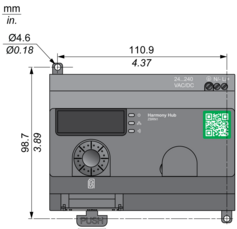
Dimensions
For your information existing access point product is now named “Harmony Hub”
Harmony Hub on a Mounting Panel
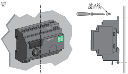
Harmony Hub is installed according to its vertical axis
Harmony Hub on DIN Rail Mounting

Clearances
Maximum Distance between Transmitter and Harmony Hub in Free Field Unobstructed

(1) Transmitter
(2) Harmony Hub
Maximum Distance between Transmitter and Harmony Hub in a Metal Enclosure with a Relay Antenna

(1) Transmitter
(3) Harmony Hub in a metal enclosure
(4) Relay antenna
Maximum Distance between Transmitter and Harmony Hub in a Metal Enclosure with a Passive Antenna
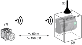
(1) Transmitter
(2) External antenna
(3) Harmony Hub in a metal enclosure
The range is reduced if the transmitter is placed in a metal enclosure (reduction factor : approx 10%)
Glass window | 10...20 % |
Plaster wall | 30...45 % |
Brick wall | 60 % |
Concrete wall | 70...80 % |
Metal structure | 50...100 % |
Harmony Hub Clearances

(1) PLC or other devices
(2) Power supply or other devices
Harmony Hub Wiring Diagram


(1) Wire sizes for Power Supply terminals (L/+, N/-)
Items usually bought together

Need more information? Check our technical FAQs!
Easily find answers to the most frequently asked questions.