Using logic, it is possible to display the individual bit values in a double word point. This is useful in protocols such as Modbus where bit packing is used to transmit data in low bandwidth systems. Here is one such example of how the individual bits may be extracted.
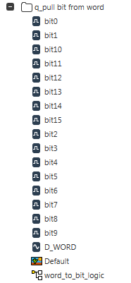
1) In this example an internal analog point has been created and named D_WORD to represent a 16-bit point. Sixteen digital points have been created and named bit0 through bit15. Along with with is the logic program (function block diagram is used for this example) as well as the mimic. The tree structure in ViewX looks like this:
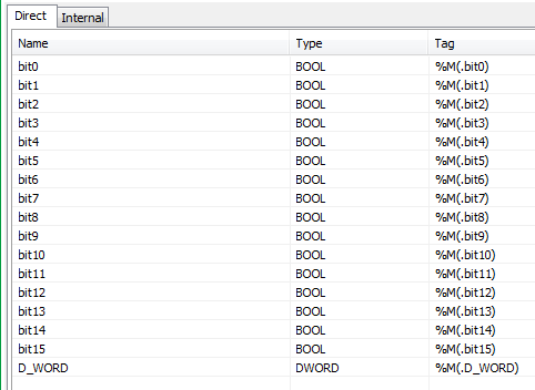
2) In the fbd logic program the analog and digital points are added to the 'Direct' table with the analog point being configured as a DWORD type and the digital points being configured as BOOLEAN types. The table looks like this:
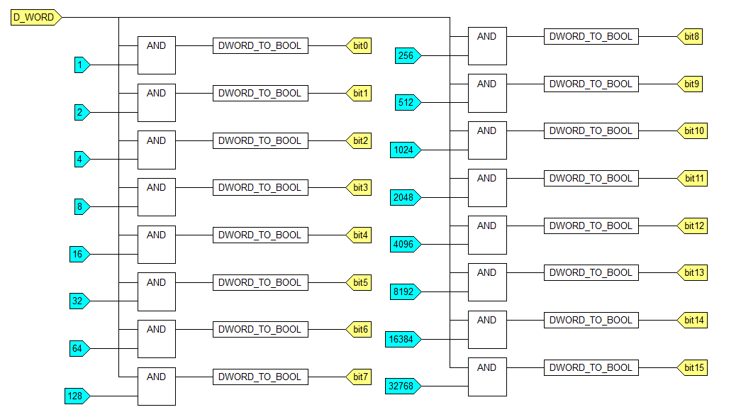
3) In the fbd logic program a series of AND function blocks act to filter out which weighted values (i.e. 'bits') are true. From here, the output of each AND function block is sent to a DWORD_TO_BOOL function block to convert the weighted value to a boolean value (0 or 1). The output of each DWORD_TO_BOOL is then sent to its corresponding digital (bit) point. The logic looks like this:
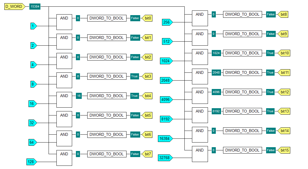
4) With the logic program in run mode, the connection values can be displayed so that all values for all points in the program may be seen. In this case the analog point has been given a value of 15384 and the corresponding digital points are shown as either FALSE or TRUE.
5) On the mimic, the analog point is shown with its value and below it is shown the individual bit values.
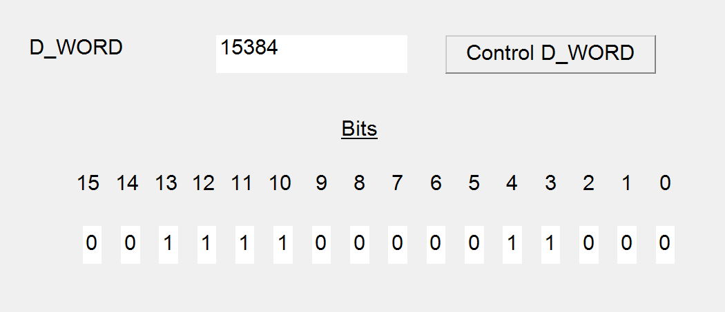
6) The logic used in this example may be found in the enclosed q_pull it from word.sde file which is save in ClearSCADA 2014 R1.1 format. Any version of ClearSCADA from version 2014 R1 or newer may import this .sde file.
1) In this example an internal analog point has been created and named D_WORD to represent a 16-bit point. Sixteen digital points have been created and named bit0 through bit15. Along with with is the logic program (function block diagram is used for this example) as well as the mimic. The tree structure in ViewX looks like this:
2) In the fbd logic program the analog and digital points are added to the 'Direct' table with the analog point being configured as a DWORD type and the digital points being configured as BOOLEAN types. The table looks like this:
3) In the fbd logic program a series of AND function blocks act to filter out which weighted values (i.e. 'bits') are true. From here, the output of each AND function block is sent to a DWORD_TO_BOOL function block to convert the weighted value to a boolean value (0 or 1). The output of each DWORD_TO_BOOL is then sent to its corresponding digital (bit) point. The logic looks like this:
4) With the logic program in run mode, the connection values can be displayed so that all values for all points in the program may be seen. In this case the analog point has been given a value of 15384 and the corresponding digital points are shown as either FALSE or TRUE.
5) On the mimic, the analog point is shown with its value and below it is shown the individual bit values.
6) The logic used in this example may be found in the enclosed q_pull it from word.sde file which is save in ClearSCADA 2014 R1.1 format. Any version of ClearSCADA from version 2014 R1 or newer may import this .sde file.


