To use the ASCO 917 or 918 with a photocell, accessory 47 is needed. Read the separate FAQ article, "How to correctly wire the accessory 47 to the ASCO 918/917?" for installation instructions.
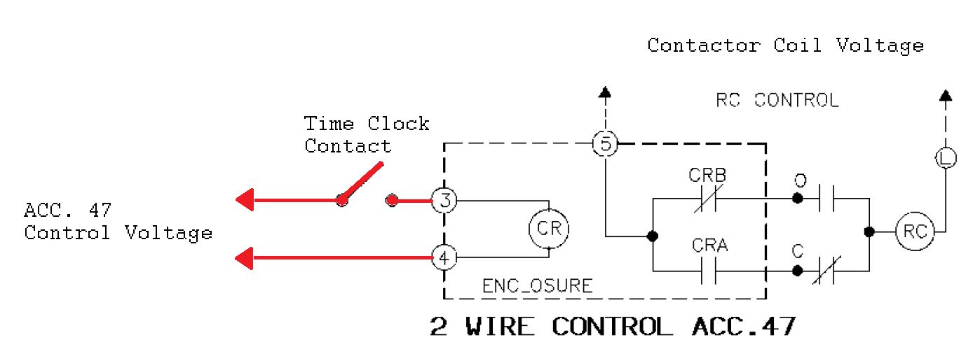
After correctly installing the accessory 47 module with the ASCO 918/917, a customer supplied time clock can become the switching device for the control of the opening and closing of the contactor. Reference the sample schematic below showing the typical connection of a time clock with the accessory 47.

After correctly installing the accessory 47 module with the ASCO 918/917, a customer supplied time clock can become the switching device for the control of the opening and closing of the contactor. Reference the sample schematic below showing the typical connection of a time clock with the accessory 47.
Released for: Schneider Electric USA


