DIA5ED2130303EN | October 2025

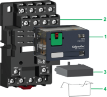
The RPM power relay range comprises:
1 15 A relay with 1, 2, 3, and 4 CO contacts
2 Sockets with mixed contact terminals
3 Protection modules (diode, RC circuit, or varistor) or 1 timer module (these protection modules are common to all sockets except for the timer module, which can be used on 3-pole or 4-pole sockets only)
4 Metal maintaining clamp for 1 and 2 CO contact relays


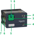
1 Spring-return pushbutton for testing the contacts (blue: DC, red: AC)
2 Mechanical “relay status” indicator
3 Removable lock-down door enabling forced maintenance of the contacts for test sequences or maintenance purposes
4 LED (depending on version) indicating the relay status
5 Removable legend for relay identification
6 4 notches for rail mounting adapter or panel mounting adapter with mounting lugs
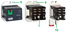
7 5, 8, 11, or 14 Faston-type pins
8 The area by which the product can be easily gripped
9 Mounting adapter enabling direct mounting of the relay on a panel
10 Mounting adapter enabling direct mounting of the relay on a 5-rail

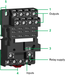
Sockets with mixed contact terminals (1)
1 Connection by screw clamp terminals
2 5, 8, 11, or 14 female contacts for the relay pins
3 Location for the protection modules or the timer module
4 Locating a slot for mounting on the rail with a mounting clip
5 2 or 4 holes for panel mounting
(1) The inputs are mixed with the relay supply, with the outputs being located on the opposite side of the socket.

