
How to size and protect Neutral on PCSN
Single phase non-linear loads Characteristics
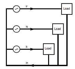
figure 1 Single phase loads
If the loads are linear, the currents constitute a balanced 3-phase system. The sum of the phase currents is therefore zero, as is the neutral current.
in = S iph = 0
If the loads are non-linear, the phase currents are non-sinusoidal and therefore contain harmonics, particularly of orders
which are multiples of 3. Since all three-phase currents are equal, the third order harmonic currents, for example, have the
same magnitude and can be written as:
ir3 = I3 sin 3(wt)
is3= I3 sin 3(wt -2p/3) = I3 sin (3wt -2p) = ir3
it3 = I3 sin 3(wt -4p/3) = I3 sin (3wt -4p) = ir3
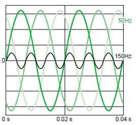
figure 2: 3-phase currents at 50Hz and 150Hz
Appearance of the current in the neutral
Figure 3 shows the currents circulating in the phases of three identical non-linear single-phase loads connected between phase and neutral, and also the resulting current in the neutral conductor.
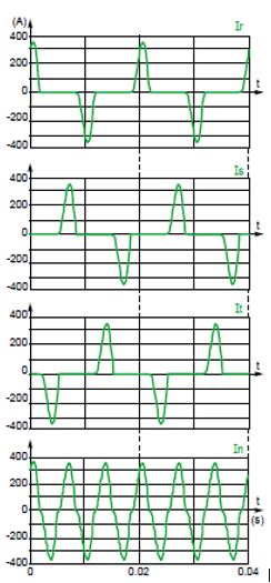
Figure 3 : Phase and neutral currents supplying non-linear single-phase loads
The spectrums for these currents are shown in figures 4 and 5. Note that the neutral current only contains odd order components which are multiples of 3 (3, 9, 15, etc), whose magnitudes are three times greater than those of the phase currents.
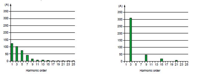
figure 4 : I non-linear single phase loads spectrum figures 5: Non-linear single-phase loads neutral current
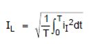
For a period T of the fundamental, a phase current consists of a positive wave and a negative wave separated by an interval where the current is zero. The rms value of the line current can be calculated using the formula:
The rms value of the neutral current can be calculated over an interval equal to T/3. During this interval, the neutral current also consists of a positive wave and a negative wave, identical to those of the phase current. The rms value of the neutral current can therefore be calculated as follows:
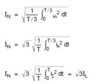
Here, therefore, the current in the neutral conductor has an rms value sqrt (3) times greater than that of the current in a phase.
When the current wave of all three phases overlaps, as in the example in figure 6, the rms value of the current in the neutral is less than sqrt(3) times the rms value of the current in a phase (see fig. 7).
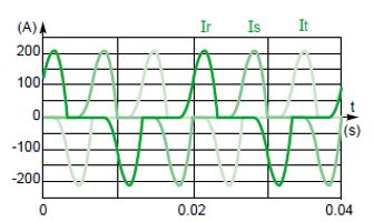
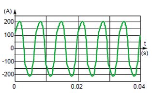
figure 6: 3 phases current figure 7: Neutral current
In installations where a large number of non-linear loads, such as switch mode power supplies for computer equipment, the current in the neutral may therefore exceed the current in each phase. This situation, although rare, requires the use of a reinforced neutral conductor.
3) Overload on the neutral conductor as a function of current distortion
Balanced loads
Considering that the third harmonic is the dominant harmonic, the distortion factor is very close to the third harmonic ratio. So: THD = i3 (%)
Moreover, as indicated in 2.1, the current in the neutral IN is very close to 3 I3. So: IN ≈ 3 I3 (A)
This can be expressed as: IN ≈ 3 i3 I1 ≈ 3 THD I1
Using the general formula:
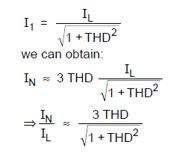
This approximate formula is only valid when the result is less than sqrt (3). The loading of the neutral current therefore varies as a function of the distortion factor as shown in the following graph (see fig. 8).
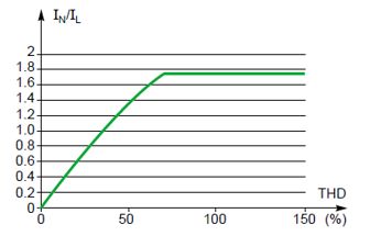
Figure 8: Neutral current (balanced loads)
Unbalanced loads
Consider the simplified system consisting of a balanced 3-phase source and two identical single- phase loads, connected between phase and neutral (see fig. 9).

Figure 9: Unbalance loads
We can demonstrate, in the same way as in 2.2, that the maximum value of the neutral current
cannot exceed sqrt (2) times the current in each phase.
If we only consider the fundamental current and the third order harmonic current of each of the loads, the current in the neutral is the sum of a fundamental current and a third order harmonic current:
_ The fundamental current is the vector sum of the fundamental currents in both loads. Since these currents are equal and phase-shifted by 120°, the resulting current is equal to the fundamental current of each of the loads.
_The third order harmonic current is the sum of all the third order harmonic currents.
Using the same formula as before, will get :
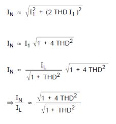
This approximate formula is only valid as long as the result is less than sqrt(2) . The loading of the neutral current therefore varies as a function of the distortion factor as shown in the following graph (see fig. 10).
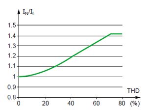
Figure 10: Neutral current (unbalanced loads)

Figure 11 : Active filter
This type of device has the capacity to compensate a harmonic current in the neutral whose magnitude is three times that of the phase current.
Example:Harmonic current per phase 30 A
Neutral harmonic current 90 A
This situation on which the neutral current would reach 3 times the filter output phase current represent a case where the filter will filtering only Harmonic 3 and multipliers . This worst case is quite rare, most of time the filter is sized and set to filter all harmonic ranks absorbed by the loads (H3, H5,.. ) and neutral current magnitude is often between 1,5 and 2 times the filter output phase current
IEC 60364 mention that Neutral is an active conductor and must be open and protected. In countries where some derogation exist a breaker 3p can be used . the phase cable and the breaker will be size for the phase current of the filter ( taking into account the coefficient of 1,25 to take into account the global thermal effect of harmonic and the neutral cable only will be oversized for 3 times the phase current
To combine advantage of size the neutral just enough and avoid any risk of breaker tripping, Accusine PCSN have a new feature named neutral limitation. Same as the phase output current, neutral output current is internally measured and regulated according to the limit ratio enter during the commissioning operation.
In the neutral current reach more than the limit define, the priority ratio between harmonic and fundamental current will be applying to reduce neutral current to the maximum value defined
- If harm mode only is enable then the harmonic compensation on the phase output current will be reduce
- If both harmonic and PFC mode are enable the correctly will be applied according to the priority target
Single phase non-linear loads Characteristics
figure 1 Single phase loads
If the loads are linear, the currents constitute a balanced 3-phase system. The sum of the phase currents is therefore zero, as is the neutral current.
in = S iph = 0
If the loads are non-linear, the phase currents are non-sinusoidal and therefore contain harmonics, particularly of orders
which are multiples of 3. Since all three-phase currents are equal, the third order harmonic currents, for example, have the
same magnitude and can be written as:
ir3 = I3 sin 3(wt)
is3= I3 sin 3(wt -2p/3) = I3 sin (3wt -2p) = ir3
it3 = I3 sin 3(wt -4p/3) = I3 sin (3wt -4p) = ir3
figure 2: 3-phase currents at 50Hz and 150Hz
Appearance of the current in the neutral
Figure 3 shows the currents circulating in the phases of three identical non-linear single-phase loads connected between phase and neutral, and also the resulting current in the neutral conductor.
Figure 3 : Phase and neutral currents supplying non-linear single-phase loads
The spectrums for these currents are shown in figures 4 and 5. Note that the neutral current only contains odd order components which are multiples of 3 (3, 9, 15, etc), whose magnitudes are three times greater than those of the phase currents.
figure 4 : I non-linear single phase loads spectrum figures 5: Non-linear single-phase loads neutral current
- Calculating the rms value of the neutral current
For a period T of the fundamental, a phase current consists of a positive wave and a negative wave separated by an interval where the current is zero. The rms value of the line current can be calculated using the formula:
The rms value of the neutral current can be calculated over an interval equal to T/3. During this interval, the neutral current also consists of a positive wave and a negative wave, identical to those of the phase current. The rms value of the neutral current can therefore be calculated as follows:
Here, therefore, the current in the neutral conductor has an rms value sqrt (3) times greater than that of the current in a phase.
When the current wave of all three phases overlaps, as in the example in figure 6, the rms value of the current in the neutral is less than sqrt(3) times the rms value of the current in a phase (see fig. 7).
figure 6: 3 phases current figure 7: Neutral current
In installations where a large number of non-linear loads, such as switch mode power supplies for computer equipment, the current in the neutral may therefore exceed the current in each phase. This situation, although rare, requires the use of a reinforced neutral conductor.
3) Overload on the neutral conductor as a function of current distortion
Balanced loads
Considering that the third harmonic is the dominant harmonic, the distortion factor is very close to the third harmonic ratio. So: THD = i3 (%)
Moreover, as indicated in 2.1, the current in the neutral IN is very close to 3 I3. So: IN ≈ 3 I3 (A)
This can be expressed as: IN ≈ 3 i3 I1 ≈ 3 THD I1
Using the general formula:
This approximate formula is only valid when the result is less than sqrt (3). The loading of the neutral current therefore varies as a function of the distortion factor as shown in the following graph (see fig. 8).
Figure 8: Neutral current (balanced loads)
Unbalanced loads
Consider the simplified system consisting of a balanced 3-phase source and two identical single- phase loads, connected between phase and neutral (see fig. 9).
Figure 9: Unbalance loads
We can demonstrate, in the same way as in 2.2, that the maximum value of the neutral current
cannot exceed sqrt (2) times the current in each phase.
If we only consider the fundamental current and the third order harmonic current of each of the loads, the current in the neutral is the sum of a fundamental current and a third order harmonic current:
_ The fundamental current is the vector sum of the fundamental currents in both loads. Since these currents are equal and phase-shifted by 120°, the resulting current is equal to the fundamental current of each of the loads.
_The third order harmonic current is the sum of all the third order harmonic currents.
Using the same formula as before, will get :
This approximate formula is only valid as long as the result is less than sqrt(2) . The loading of the neutral current therefore varies as a function of the distortion factor as shown in the following graph (see fig. 10).
Figure 10: Neutral current (unbalanced loads)
- Filtering devices
Figure 11 : Active filter
This type of device has the capacity to compensate a harmonic current in the neutral whose magnitude is three times that of the phase current.
Example:Harmonic current per phase 30 A
Neutral harmonic current 90 A
This situation on which the neutral current would reach 3 times the filter output phase current represent a case where the filter will filtering only Harmonic 3 and multipliers . This worst case is quite rare, most of time the filter is sized and set to filter all harmonic ranks absorbed by the loads (H3, H5,.. ) and neutral current magnitude is often between 1,5 and 2 times the filter output phase current
- Active filter classical Neutral sizing
- If we use a 4p breaker ( with trip unit 3d or 4d) , the breaker rating must size for the neutral current so for 3 times the filter phase capacity .
- If the breaker is a 4p 4d , the phase cable must be oversized also ;
- if the breaker is a 4p 3d , the phase cable can be size according to the trip unit setting
IEC 60364 mention that Neutral is an active conductor and must be open and protected. In countries where some derogation exist a breaker 3p can be used . the phase cable and the breaker will be size for the phase current of the filter ( taking into account the coefficient of 1,25 to take into account the global thermal effect of harmonic and the neutral cable only will be oversized for 3 times the phase current
- PCSN neutral limitation
To combine advantage of size the neutral just enough and avoid any risk of breaker tripping, Accusine PCSN have a new feature named neutral limitation. Same as the phase output current, neutral output current is internally measured and regulated according to the limit ratio enter during the commissioning operation.
In the neutral current reach more than the limit define, the priority ratio between harmonic and fundamental current will be applying to reduce neutral current to the maximum value defined
- If harm mode only is enable then the harmonic compensation on the phase output current will be reduce
- If both harmonic and PFC mode are enable the correctly will be applied according to the priority target